Table of Contents
Advertisement
Quick Links
Advertisement
Table of Contents

Subscribe to Our Youtube Channel
Related Manuals for TELEDYNE OLDHAM SIMTRONICS MX 16


Summary of Contents for TELEDYNE OLDHAM SIMTRONICS MX 16
- Page 1 MX 16 ANALOG AND DIGITAL CONTROLLER NP16EN Revision D.0 NPM16EN Revision A.0...
- Page 2 User Manuals in other languages are available on Website https://teledynegasandflamedetection.com Copyright April 2021 by TELEDYNE OLDHAM SIMTRONICS S.A.S. All rights reserved. The reproduction of all or any section of this document in any form whatsoever without the written permission of TELEDYNE OLDHAM SIMTRONICS S.A.S. is forbidden.
-
Page 3: Table Of Contents
Important Information ..................2 Liability Limits ....................... 3 Warranty ........................ 3 General Introduction ................5 Purpose of the MX 16 controller ..............5 The different Versions ..................6 Firmplate ....................... 7 The COM 16 Software ..................8 Mechanical Installation ..............9 MX 16 Controller .................... - Page 4 12 Specific conditions of use and Functional Safety ....53 12.1 Specific Conditions of Use ................53 12.2 Specific instructions for the prevention of explosions ......53 12.3 Connecting detectors other than TELEDYNE OLDHAM SIMTRONICS detectors to the MX 16 controller ........54 NPM16EN Revision A.0...
-
Page 5: General Information
MX 16 ANALOG AND DIGITAL CONTROLLER USER MANUAL General Information WARNING: ALL INDIVIDUALS WHO HAVE OR WILL HAVE RESPONSIBILITY FOR USING, MAINTAINING, OR SERVICING THIS PRODUCT MUST READ THIS ENTIRE MANUAL CAREFULLY. FAILURE TO USE THIS EQUIPMENT PROPERLY COULD RESULT IN SERIOUS INJURY OR DEATH. -
Page 6: Safety Instructions
MX 16 ANALOG AND DIGITAL CONTROLLER USER MANUAL Icon Significance This symbol denotes: Attention! In the present mode of use, failure to adhere to the instructions preceded by this symbol can result in a risk of electric shock and/or death. -
Page 7: Liability Limits
MX 16 ANALOG AND DIGITAL CONTROLLER USER MANUAL Liability Limits Neither TELEDYNE OLDHAM SIMTRONICS nor any other associated company under any circumstances can be held liable for any damage, including, without limitations, damages for MX 16 loss or interruption of manufacture, loss of information, defect of the... - Page 8 MX 16 ANALOG AND DIGITAL CONTROLLER USER MANUAL NPM16EN Revision A.0...
-
Page 9: General Introduction
MX 16 ANALOG AND DIGITAL CONTROLLER USER MANUAL General Introduction MX 16 Purpose of the controller This controller is intended for the continuous measurement and control of the gases present in the atmosphere. MX 16 Figure 1: and examples of the modules The system primarily comprises : •... -
Page 10: The Different Versions
Analog and Digital versions, configurable with Wheatstone The MX 16 does not have an input for Wheatstone bridge sensors ( bridge version The MX16 does not manage MX 32 and MX 43 module as 8 analog input (AIM), 4 or 8 relais modules (ROM), 16 logic inputs (LIM) and 4 analog outputs. -
Page 11: Firmplate
MX 16 ANALOG AND DIGITAL CONTROLLER USER MANUAL Maximum Capacity Version Detectors 1 digital line 1 analog line Table 1: Summary of the maximum capacity as per the controller type • Firmplate It contains relevant information with respect to the controller version. -
Page 12: The Com 16 Software
MX 16 ANALOG AND DIGITAL CONTROLLER USER MANUAL Tag. Description Product Name Part Number Serial Number. The first four digits (in this case 2011) correspond to the year and the month of manufacture (20 and 11 indicating manufacturing in November 2020) -
Page 13: Mechanical Installation
MX 16 ANALOG AND DIGITAL CONTROLLER USER MANUAL Mechanical Installation MX 16 Controller 3.1.1 Location MX 16 is intended for indoor use only and shall be installed in premises without explosive atmospheres, away from direct exposure to sunlight, and protected from humidity, dust, and temperature variations. -
Page 14: Gas Detectors
MX 16 ANALOG AND DIGITAL CONTROLLER USER MANUAL Gas detectors Refer to the manual supplied with each detector. 3.2.1 Location Each detector shall be positioned at ground level, on the ceiling, at human height or near air extraction ducts, depending on the density of the gas to be detected or the application. Heavy gases are detected close to the ground, while lighter gases are present along the ceiling. -
Page 15: The Mx 16 Controller
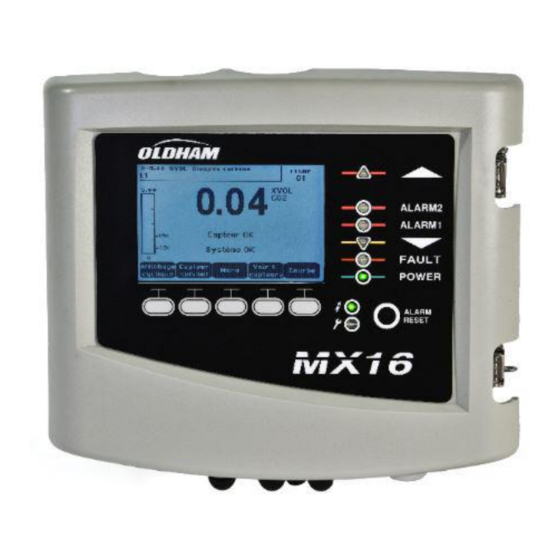
MX 16 ANALOG AND DIGITAL CONTROLLER USER MANUAL The MX 16 Controller Overview of the Unit 4.1.1 External view Figure 6: External view Rep. Function Rep. Function Monochromatic, back-lit graphic Alarm Acknowledgement button LCD display Channel status indicator Failure/maintenance indicator... - Page 16 MX 16 ANALOG AND DIGITAL CONTROLLER USER MANUAL 4.1.2 Internal view Figure 7: Internal view Rep. Function LCD graphic display card USB programmation port Programming (or mode) selector MX 16 in normal operation. 1. Read/Write configuration program MX 16 firmware update via a PC...
- Page 17 MX 16 ANALOG AND DIGITAL CONTROLLER USER MANUAL Rep. Function Cable glands; 5 x M16 + 2 x M20 Line terminal Digital communication status LED indicators (Line #1 on left, Line #2 on right). The information displayed by each pair of LEDs is interpreted as follows:...
-
Page 18: Front Plate
MX 16 ANALOG AND DIGITAL CONTROLLER USER MANUAL Rep. Function . Reset Inhibit: Minimum time of activation, adjustable from 0 to 900 seconds. . Automatic reset: Time adjustable between 15 and 900 seconds, beyond which the buzzer relay is automatically deactivated. - Page 19 MX 16 ANALOG AND DIGITAL CONTROLLER USER MANUAL Figure 9: Display of the measurement (on the left) or parameter settings display (on the right) Menus Refer to paragraph on page 23 for more details about the information that are available on the screen.
-
Page 20: Alarm Thresholds And Relays
MX 16 ANALOG AND DIGITAL CONTROLLER USER MANUAL Icon Function FAULT Orange failure indicator Off: No Fault • Solidt: Communication problem with one of the modules or invalid detector measurement, that is to say either below -10% of the range or above 110% of the range. - Page 21 MX 16 ANALOG AND DIGITAL CONTROLLER USER MANUAL • 1 Fault relay is available. This relay is not configurable and is activated on the appearance of any failure. The Fault relay is powered in normal operation mode so it does switch over in the event of a power supply failure.
- Page 22 MX 16 ANALOG AND DIGITAL CONTROLLER USER MANUAL 4.3.4 Alarms Manual Acknowledgement In this mode, Alarms must be reset by the operator. Alarm management (relays, visual indicators, buzzer) is as follows: Alarm Relay Alarm Relay Internal Event Display Alarm LED...
-
Page 23: Wiring And Electrical Connections
MX 16 ANALOG AND DIGITAL CONTROLLER USER MANUAL Wiring and Electrical Connections MX 16 This chapter details the electrical connections of all components of the system ( additional equipment). Controller Connection The electrical connections must be carried out by qualified personnel in compliance with the different directives in force in the country of installation. - Page 24 MX 16 ANALOG AND DIGITAL CONTROLLER USER MANUAL The main power shall be connected to the terminal block as indicated in Figure 10. The ground conductor shall be connected to the ground terminal . Connect earth before connecting L/N conductors. Disconnect earth after disconnecting L/N conductors.
- Page 25 MX 16 ANALOG AND DIGITAL CONTROLLER USER MANUAL 5.1.4 Digital line The cabling of the digital lines connecting the controller to the detector deployed along the line is the subject as follows. It should be remembered that this cable comes in 2 twisted pairs of 4 x 0.22 m² minimum, type MPI-22A, nominal impedance of 100 Ohms.
- Page 26 MX 16 ANALOG AND DIGITAL CONTROLLER USER MANUAL 5.1.6 Internal alarm relays MX 16 has 5 internal relays: Output Function Programmable Alarm Relay Programmable Alarm Relay Failure :(Fault) Non-programmable common relay, energized, activated upon the presence MX 16 of a failure in the (detector and/or module, system failure, etc.).
-
Page 27: Menus
MX 16 ANALOG AND DIGITAL CONTROLLER USER MANUAL Menus General Menu Tree The following figure shows the general tree of the group of menus. See page 24 ↓ See page 25 ↓ ↓ ↓ 1 SYSTEM 2 PROGRAM 3 CALIBRATION... -
Page 28: Navigation Key Functions
MX 16 ANALOG AND DIGITAL CONTROLLER USER MANUAL Navigation Key Functions Function Vertical displacement in the selected menu block. Horizontal displacement between two menu blocks. Enter Validation of the selected line. Escape Return to previous screen. Table 4: Function of the navigation keys... -
Page 29: Main Menu
MX 16 ANALOG AND DIGITAL CONTROLLER USER MANUAL Ref. Significance Function keys. ■ Menu: Display of main menu See paragraph "Main menu" on page 25. • ■ Curve: Display of the measurement curves of the last 10 days (Figure 18). The ... -
Page 30: System
MX 16 ANALOG AND DIGITAL CONTROLLER USER MANUAL System ■ 1. System Info bootloader Displays the version of the program, the (internal micro- software for loading the program), and the configuration, as well as software application verifications. ■ 2. Passwords The controller is protected by two access codes, both set at 1000 by default upon leaving the factory. -
Page 31: Calibration
Note: Only analog detectors that are not equipped with a local display can be calibrated from the MX 16 controller. For the other detectors, the menu “Sel. Detector” only makes it possible to put them in calibration mode so that they do not activate alarms during their manual calibration. - Page 32 MX 16 ANALOG AND DIGITAL CONTROLLER USER MANUAL Figure 20: Example of the “Select detectors” screen 6.7.2 2. Start Recording • Yes: Launches the recording of calibration measurements for the detector. From this moment onwards, all the calibration measurements are recorded for the detector. “Start recording”...
- Page 33 MX 16 ANALOG AND DIGITAL CONTROLLER USER MANUAL Figure 21: Adjustment of zero (left) and sensitivity (right) Operating mode 1. Press Validate. Zero calibration The Zoom command is active. Select the area of interest of the curve with the and keys. Press Zoom + up to the activation of the Zero command.
-
Page 34: Maintenance
MX 16 ANALOG AND DIGITAL CONTROLLER USER MANUAL Record the calibration The message “Do you want to validate zero and detector sensitivity?” is displayed. Press Validate calibration to confirm the adjustment of zero and sensitivity or Esc to exit the procedure. -
Page 35: Information
MX 16 ANALOG AND DIGITAL CONTROLLER USER MANUAL 6.8.4 4. Simulation Upon its selection, the message “The controller no longer ensures detection” is displayed. • The controller no longer keeps account of inputs (detector). • The simulation measurements/status initialized current measurement/status values. - Page 36 MX 16 ANALOG AND DIGITAL CONTROLLER USER MANUAL Detector in level 2 alarm Detector in OVS alarm Table 5: Gas alarm file messages. 2. Fault records This displays, for the detector c: event type (UDS = Under-scale), RANGE = measurement out of range, DEF =Failure, DOUBT = clear doubt), status (activated = ON or deactivated = OFF) as well as the date and time of appearance or release.
- Page 37 MX 16 ANALOG AND DIGITAL CONTROLLER USER MANUAL Message Significance MX 16 Acknowledgement by the acknowledgement button on the front plate of MX 1616 Simulation Switch to simulation mode Calibration At least one of the detectors is selected in calibration mode.
- Page 38 MX 16 ANALOG AND DIGITAL CONTROLLER USER MANUAL MX 16 off voltage Self-testing Failure of internal tests failure Other Contact Post-Sales Service messages Table 10: System incidents file messages 6.9.3 3. Slave info These data enable maintenance technicians to visualize the communication framework between MX 16 and the digital detector.
-
Page 39: Main Part Numbers
MX 16 ANALOG AND DIGITAL CONTROLLER USER MANUAL Main Part Numbers Reference Description MX16-0-0-0-0-0 Controller MX16, Analog or digital MX16-0-0-1-0-0 Controller MX16, Analog or digital, with RS485 output Description Reference Image RS485 commnication board 6 451 680 100-240Vac/24Vdc Power Supply 6 314 210 Fuse F7 (4A time-delay, 8.4A for 120... - Page 40 MX 16 ANALOG AND DIGITAL CONTROLLER USER MANUAL NPM16EN Revision A.0...
-
Page 41: Cleaning And Maintenance
(see Chapter 7 for the list of spare parts). The controller must be first switched off. Power on the controller once the battery has been replaced. TELEDYNE OLDHAM SIMTRONICS does not allow any other repairs than those listed here above. - Page 42 MX 16 ANALOG AND DIGITAL CONTROLLER USER MANUAL NPM16EN Revision A.0...
-
Page 43: Certificate Of Compliance
MX 16 ANALOG AND DIGITAL CONTROLLER USER MANUAL Certificate of Compliance The document hereafter (1 page) reproduces the EU declaration of conformity. NPM16EN Revision A.0... - Page 44 MX 16 ANALOG AND DIGITAL CONTROLLER USER MANUAL NPM16EN Revision A.0...
-
Page 45: 10 Technical Specifications
MX 16 ANALOG AND DIGITAL CONTROLLER USER MANUAL 10 Technical Specifications MX 16 10.1 Controller Function Function Gas Detection Controller Number of lines 1 (1 detector) Display and indicators Display Back-lit graphic LCD Status indicators - 6 LEDs - 1 Power On/Off visual indicator... - Page 46 MX 16 ANALOG AND DIGITAL CONTROLLER USER MANUAL Electrical characteristics ■ AC power supply 100 to 240Vac, 50/60 Hz ■ Maximum 24Vdc output current 1.5A with derating (see next page) Mechanical characteristics ■ Installation Wall-mounted format. Indoors use only. ■...
- Page 47 MX 16 ANALOG AND DIGITAL CONTROLLER USER MANUAL Nominal voltage 22 to 28 V on external DC Maximum load ■ 1A total with internal AC power according to T below Maximum power supply requires derating (in order to maintain a constant internal...
- Page 48 MX 16 ANALOG AND DIGITAL CONTROLLER USER MANUAL NPM16EN Revision A.0...
-
Page 49: 11 Rs485 Digital Output
MX 16 ANALOG AND DIGITAL CONTROLLER USER MANUAL 11 RS485 Digital Output MX 16 RS485 Modbus units using the option are equipped with a communication card (code 6451680), which is affixed to the motherboard. This card generates a RS485 output in Modbus RTU format. -
Page 50: Transfer Table
MX 16 ANALOG AND DIGITAL CONTROLLER USER MANUAL 11.2 Transfer Table Two types of information can be retrieved the RS485 output: • Information about sensor configuration; • Real-time sensor information (measurements, alarms, etc.). 11.2.1 1. Access to configuration information It is possible to access the installation configuration (for example, to access the alarm thresholds or the names of the sensors). -
Page 51: Address Table
MX 16 ANALOG AND DIGITAL CONTROLLER USER MANUAL 11.2.1 2. Access to real-time information Measurement and alarm information from the detectors is listed in the transfer table from address 2000 to 65535. The sensor measurements are available at addresses 2001 to 2264, the sensor statuses are available at addresses 2301 to 2564 (alarm 1, alarm 2, etc.). - Page 52 MX 16 ANALOG AND DIGITAL CONTROLLER USER MANUAL the slave configuration outlined below. 2000 From addresses 2000 to 65535 the address management Modbus is typical address management. Standard address management. 65535 11.3.2 Configuring sensors Downloading the configuration MX 16 uses 1 external addresses (line #1 channel #1 and 257 analog channels for which the addresses are located from 257 to 258.
- Page 53 MX 16 ANALOG AND DIGITAL CONTROLLER USER MANUAL Address SENSORS Data type [64 + 2] bytes 1 Com sensor 2 X 16 Unicode text (16 bits) 16 characters including the final 17 Status Start / Stop: if in operation, variable = 1. If stopped, variable = 0.
- Page 54 MX 16 ANALOG AND DIGITAL CONTROLLER USER MANUAL 0 = inactive 1 = active 67 Acknowl Manual acknowl Al 1, 2, 3, Configuration per bit bit7 bit6 bit5 bit4 bit3 bit2 bit1 bit 0 alarm? verification (Auto/manu) Verification 1 = Manual acknowl and 0 = Automatic Acknowl.
- Page 55 MX 16 ANALOG AND DIGITAL CONTROLLER USER MANUAL 11.3.3 Acquisitions retrieved cyclically Real address SENSOR Data type MEASUREMENTS [256 bytes + 8] Table with 66 signed integer of 16 bits where If digital Sensor measurement the measurements are listed at their address. The...
- Page 56 MX 16 ANALOG AND DIGITAL CONTROLLER USER MANUAL NPM16EN Revision A.0...
-
Page 57: Specific Conditions Of Use And Functional Safety
MX 16 ANALOG AND DIGITAL CONTROLLER USER MANUAL 12 Specific conditions of use and Functional Safety 12.1 Specific Conditions of Use The safety function of the MX 16 is the processing of the signal of the detectors linked to its input. -
Page 58: Connecting Detectors Other Than Teledyne Oldham
MX 16 ANALOG AND DIGITAL CONTROLLER USER MANUAL • In the event the user connects a non-TELEDYNE OLDHAM SIMTRONICS brand detector MX 16 to the controller, the user must ensure that the detector is compatible with the input characteristics of the controller, so that the information delivered by the detector will be properly interpreted (see transfer curve on the following page). - Page 59 MX 16 ANALOG AND DIGITAL CONTROLLER USER MANUAL properly interpreted. In addition, the controller must provide sufficient supply voltage, taking into account voltage drops in the cable. MX 16 Detector signal ouput Status 0 to 2.4 mA Fault >2.4 to 21.6mA Measurement >21.6 mA...
- Page 60 CYPRESS Z.I. Est – CS 20417 SHANGHAI TX 77429, 62027 ARRAS Cedex, CHINA FRANCE Tel.: +86-134-8229-5057 Tel.: +1-713-559-9200 Tel.: +33 (0)3 21 60 80 80 www.teledynegasandflamedetection.com © 2021 Teledyne Oldham Simtronics. All right reserved. NPM16EN Revision A.0. / April 2021...
Need help?
Do you have a question about the MX 16 and is the answer not in the manual?
Questions and answers