
Subscribe to Our Youtube Channel
Related Manuals for Convotherm 6.06 mini


Summary of Contents for Convotherm 6.06 mini
- Page 1 Combi Oven Convotherm mini OES mini 6.06, 6.10, 10.10 Installation Manual UL, USA - Original, ENG Advancing Your Ambitions...
- Page 3 WARNING Disconnect power at the main external power switch before servicing or repairing a combi oven. IMPORTANT ALL SERVICE MUST BE PERFORMED BY A QUALIFIED CONVOTHERM AUTHORIZED TECHNI‐ CIAN. KEEP AREA FREE AND CLEAR OF COMBUSTIBLES. Installation Installation of this unit must be done by a licensed professional when installed in the Commonwealth ■...
-
Page 5: Table Of Contents
Table of Contents Table of Contents General Environmental Protection Identifying Your Combi Oven Customer Documentation Structure About This Installation Manual Safety Information That Must Be Read without Exception Configuration and Functions The Combi Oven's Configuration and Functions Control Panel Layout and Functions For Your Safety Basic Safety Instructions Your Combi Oven's Intended Use... - Page 6 Table of Contents Placing into operation Working Safely When Putting the Unit Into Operation Procedure for Placing the Unit into Operation Removing from Service and Disposal Removing from Service and Disposal Technical data Dimensions and weights Maximum permissible loading weight Electrical supply Heat loss Water connections...
-
Page 7: General
1 General 1 General 1.1 Environmental Protection Policy statement Our customers' expectations, the legal regulations and standards we have to follow, and our compa‐ ny's reputation are what drives the quality and service behind all our products. Our environmental management policy is not only designed to ensure that we are always in full com‐ pliance with all environmental laws and regulations, but also reflects our commitment to the environ‐... -
Page 8: Identifying Your Combi Oven
1 General 1.2 Identifying Your Combi Oven Nameplate location The nameplate is found on the left side of the combi oven. Nameplate layout and structure Designation Unit name Combi Steamer Trade name Letters Meaning Electrical units with water injection xx.yy numbers Unit size mini Series... -
Page 9: Customer Documentation Structure
1 General 1.3 Customer Documentation Structure Unit documentation parts Document type Contents Installation manual Describes how to transport, set up, install, and put the unit into opera‐ ■ tion Goes over all the hazards involved in the various installation activities ■ and how to prevent and/or counter them Contains technical specifications ■... -
Page 10: Safety Information That Must Be Read Without Exception
1 General 1.5 Safety Information That Must Be Read without Exception Safety information found in the documentation for the customer Only the installation manual and operating manual provide safety information for the combi oven. The installation manual provides safety information for the transportation, setup, installation, placing- into-operation, and removal-from-service tasks it describes. -
Page 11: Configuration And Functions
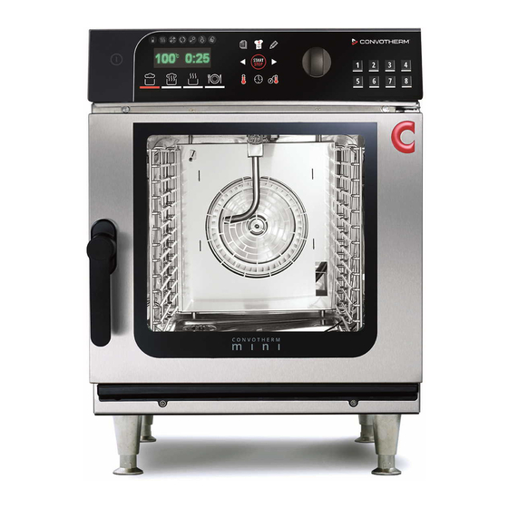
2 Configuration and Functions 2 Configuration and Functions 2.1 The Combi Oven's Configuration and Functions Parts and functions The figure below shows a size 6.10 mini combi oven used as an example representing all models: Designation Function Ventilation port Draws in ambient air in order to remove moisture from the oven cavity Air vent Lets hot steam escape... - Page 12 2 Configuration and Functions Designation Function Unit feet Used to set up and level the unit Nameplate Used to identify the unit Material The unit's inner and outer parts are made of stainless steel. Installation Manual...
-
Page 13: Control Panel Layout And Functions
2 Configuration and Functions 2.2 Control Panel Layout and Functions Control panel layout and parts (standard) Designation Function Unit ON/OFF Used to turn the combi oven on and off switch Display and program se‐ Shows the active cooking program and the selected extra ■... -
Page 14: For Your Safety
3 For Your Safety 3 For Your Safety Purpose of this section The purpose of this section is to provide you with all the information you will need in order to safely work with/on the combi oven without putting yourself and others at risk. Read this section very carefully! 3.1 ... - Page 15 3 For Your Safety For more information... Related subjects Your Combi Oven's Intended Use Warning Labels on the Combi Oven Hazards posed by the unit Safety Devices Staff and Work Area Requirements Personal protective equipment Installation Manual...
-
Page 16: Your Combi Oven's Intended Use
3 For Your Safety 3.2 Your Combi Oven's Intended Use The combi oven's intended use The combi oven has been designed and built exclusively for cooking a variety of food in standard- ■ size food containers (steam table pans, sheet pans, etc.). Steam, convection, and combi-steam (steam superheated without pressure) are used for this purpose. - Page 17 3 For Your Safety Prerequisites for cleaning Only use the cleaning agents approved by the manufacturer. ■ Only use the cleaning tools specified by the manufacturer; please refer to 'Cleaning schedule' in ■ the operating manual. Do NOT use a pressure washer to clean the unit. ■...
-
Page 18: Warning Labels On The Combi Oven
3 For Your Safety 3.3 Warning Labels on the Combi Oven Warning label location The figure below shows a size 6.10 mini combi oven used as an example representing all models: Warning labels on unit door Warning labels (1) on the unit door: Warning Description Hot surface warning... - Page 19 3 For Your Safety Warning labels on combi oven case Warning labels (2) on combi oven case: Warning Description WARNING To reduce the risk of electric shock, do not remove or open cover. No user serviceable parts inside. Refer servicing to qualified personnel. Disconnect power supply before servicing.
-
Page 20: Obligations Of Owners And Personnel With The Authority To Issue Instructions In The
Electrical assembly, placement-into-operation, servicing, maintenance, repair, and testing work on the combi ovens must be carried out exclusively by authorized service companies in conformity with the placement-into-operation, servicing, maintenance, and repair documents specified by Convotherm. The required activities must be carried out exclusively by qualified electricians who have the required training and current professional experience and who have the necessary familiarity with all applicable standards, regulations, and accident prevention regulations. -
Page 21: Hazards Posed By The Unit
3 For Your Safety 3.5 Hazards posed by the unit General rules when using the unit The combi oven has been designed in such a way as to ensure that users will be protected from all hazards that can be reasonably prevented using design-based measures. However, the combi oven's intended use entails a series of residual risks that will require you to take precautions in order to avoid them. - Page 22 3 For Your Safety Contact with cleaning agents The unit can pose the following hazards during all installation work: Skin, eye, and respiratory tract irritation hazard as a result of contact with cleaning agents and their vapors When? When installing the cleaning system ■...
-
Page 23: Safety Devices
3 For Your Safety 3.6 Safety Devices Meaning The combi oven features a series of safety devices and guards that protect the user from a variety of hazards. All safety devices and guards must be present, fully functional, and locked properly without exception when the combi oven is being used. - Page 24 3 For Your Safety Guard or safety device Function Check Oven cavity safety ther‐ Turns off the unit if the temper‐ An error code will be output in mostat ature exceeds the allowable the event of a fault (not limit (Contact a service company shown) that is authorized to reset the...
-
Page 25: Staff And Work Area Requirements
3 For Your Safety 3.7 Staff and Work Area Requirements Staff requirements The table below specifies the qualifications needed for each role. Provided that they have the required qualifications, a single person can take over more than one role if necessary. Role Required qualifications Tasks... - Page 26 3 For Your Safety Work areas during installation and placement into operation During installation and placement into operation, the work area for staff will be the entire area occu‐ pied by the unit and its surroundings. Installation Manual...
-
Page 27: Personal Protective Equipment
3 For Your Safety 3.8 Personal protective equipment Transportation and setup Task Tools used Personal Protective Equipment Transporting the unit within the fa‐ Appropriate lifting Protective gloves ■ ■ ■ cilities equipment Safety footwear ■ Setting up the unit on a work table Carrying straps (for A hard hat (e. -
Page 28: Transportation
The following table lists the dimensions for the units together with their packaging. This list can be used to figure out the required minimum door width and height required in order to be able to get the unit to its intended installation location: 6.06 mini 6.10 mini 10.10 mini [in] 22.8... -
Page 29: Included Equipment And Parts
4 Transportation 4.3 Included equipment and parts Unit and accessories The unit scope consists of the following parts: One combi oven ■ One left-hand side rack ■ One right-hand side rack ■ Documents The following documents are enclosed with the unit: One installation manual ■... -
Page 30: Setup
5 Setup 5 Setup 5.1 Adjacent Systems Handling exhaust air During operation, the combi oven will produce heat and moisture, most of which will escape upwards into the ambient air in the form of hot steam coming through the air vent. Do not connect any lines or ducts directly to the combi oven's air vent! The manufacturer recommends removing this exhaust air from the combi oven's working area with a range hood or ventilated ceiling. -
Page 31: Installation Location Requirements
5 Setup 5.2 Installation location requirements Meaning This section provides information on how to choose a suitable installation location for the unit. Careful‐ ly check the intended installation location to make sure it is adequate before bringing the unit there and starting with the installation! Setup standards and regulations All national, state, and local standards and regulations concerning commercial kitchen operations must be complied with. - Page 32 Maximum cleaning agent weight (with ConvoClean / Convoclean+ option only) ■ The weight of the stand or work table ■ Add the following individual weights to calculate the total unit weight: 6.06 mini 6.10 mini 10.10 mini Individual weights The combi oven's empty weight...
- Page 33 The safety clearances on the left, right, and rear must be maintained without exception. The figure below shows a size 6.10 mini combi oven used as an example representing all models: 180° 90° B‘ 6.06 mini 6.10 mini 10.10 mini Meaning Minimum required space for the unit width when [in] 24.9...
- Page 34 5 Setup Required space – height The figure below shows a size 6.10 mini combi oven used as an example representing all models: The service technician responsible for setting up the unit must take into account the ceiling's proper‐ ties and any adjacent systems being used (air ventilation system, range hood) when determining the actual clearance required between the top of the unit and the ceiling.
-
Page 35: Removing The Unit From The Pallet (10.10 Mini)
5 Setup 5.3 Removing the unit from the pallet (10.10 mini) Rules for safely lifting the unit Observe the following rules in order to prevent the unit from toppling over: The unit must be carefully lifted and secured in such a way that it will not tip over. ■... -
Page 36: Setting Up The Unit On A Work Table
5 Setup 5.4 Setting up the unit on a work table Rules for safely setting up the unit Observe the following rules in order to ensure that the unit will have the required stability: It must be possible to set up the work table at the installation location in such a way that it will not ■... -
Page 37: Setting Up The Unit On A Stand
5 Setup 5.5 Setting Up the Unit on a Stand Rules for safely setting up the unit Observe the following rules in order to ensure that the unit will have the required stability: The unit's equipment stand must be secured in such a way that it cannot topple over if it is subjec‐ ■... - Page 38 5 Setup Use the enclosed screws (5) to screw the unit onto the equipment stand from below. Position the device with the stand and use the height-ad‐ justable feet to level the stand. Use a spirit level to make sure that the unit is properly leveled.
-
Page 39: Setting Up Units In A Stacking Kit
5 Setup 5.6 Setting Up Units in a Stacking Kit Rules for safely setting up the units in a stacking kit Observe the following rules in order to ensure that the stacking kit with the units will have the required stability: Make sure that the units placed on the top and bottom of the stacking kit are similar in terms of ■... -
Page 40: Installation
6 Installation 6 Installation 6.1 Electrical installation 6.1.1 Planning the Electrical Installation Meaning It is crucial for the unit's electrical system to be carefully and correctly installed in order for the unit to run safely and without any problems. All the rules and specifications specified in this section, as well as the procedures described, must be followed to the letter. - Page 41 6 Installation Power supply The power cord must have the following characteristics: Listed, type SO, SOO, STO, STOO, SEO, SJO, SJOO, SJTO, SJTOO, SJEO, HSO, HSOO, ■ HSJO, or HSJOO with or without suffix W. Between two to six feet long for counter top mounted or three to ten feet long for floor mounted ■...
-
Page 42: Performing The Electrical Installation
6 Installation 6.1.2 Performing the Electrical Installation Prerequisites Check whether the following prerequisite is met: The unit's connection point has been de-energized and locked and tagged out. ■ Performing the Electrical Installation Connect the unit to the equipotential bonding system at the intended connection point (1). -
Page 43: Network Connection
6 Installation 6.2 Network Connection 6.2.1 Planning the Network Connection Meaning It is crucial for the unit's network connection to be carefully and correctly installed in order for the unit to run safely and without any problems and to have the connection to the Internet required for this pur‐ pose. -
Page 44: Making The Network Connection
6 Installation 6.3 Making the Network Connection Installation steps To establish an Internet connection, follow the steps below: Use a network cable to connect the combi oven’s network port to the network jack preinstalled and intended for this use by the customer. When placing the combi oven into operation, check wheth‐... -
Page 45: Water Connection
6 Installation 6.4 Water connection 6.4.1 Water supply Water connection standards and regulations Make sure to comply with all national and state laws and regulations that apply to the water connec‐ tion, as well as with all applicable local requirements and regulations set forth by the relevant local wa‐ ter utilities and authorities. - Page 46 6 Installation Connection diagram with water treatment system 4 - 20 °d H 4 - 7 ° dH 7 - 27 °T H 7 - 13 °T H 5 - 19 °e 5 - 9 ° e 70 - 125 ppm 70 - 270 ppm 0, 7 - 1, 3 m mo l/l 0, 7 - 2, 7 m mo l/l...
- Page 47 6 Installation Installing the water supply connection Flush the water connection on the on-site water line (Z). Install the sediment filter (X) and, if necessary, a water treatment system (W). Install a separate shut-off device with a mesh strainer for each unit (Y or Y Install an appropriate backflow preventer (V) in the water supply line if required by local regulations.
-
Page 48: Checking The Water Quality
6 Installation 6.4.2 Checking the water quality Required tools: You will need the following tools: 1 sample jar for getting a sample ■ 1 conductivity meter (part No. 3019007) ■ A general hardness and carbonate hardness analysis kit, including two beakers (part No. 3019010) ■... -
Page 49: Drain Connection
6 Installation 6.4.3 Drain connection Drain connection standards and regulations Make sure to comply with all national and state laws and regulations, as well as with all applicable lo‐ cal requirements and regulations set forth by the relevant local utilities and authorities, that apply to the drain connection and to the wastewater's properties. - Page 50 6 Installation Connection diagram The figure below shows a size 6.10 mini combi oven used as an example representing all models: 5% (3°) Designation Function Drain Connection At the back of the unit, connection point C – please refer to 'Connec‐ tion drawing' on page 64 Safety overflow At the bottom of the unit, connection point M –...
-
Page 51: Installing The Convoclean System (For Units With Convoclean / Convoclean+)
6 Installation 6.5 Installing the ConvoClean System (for Units with ConvoClean / ConvoClean+) 6.5.1 Components of Fully Automatic Oven Cleaning System Cleaning agents and rinse aid Only use the products specified here in order to clean the combi oven. NOTICE! The warranty will be void if there is any damage that can be traced back to the use of incor‐ rect cleaning agents. -
Page 52: Connecting The Fully Automatic Cleaning System
6 Installation 6.5.2 Connecting the Fully Automatic Cleaning System Rules for safely connecting the fully automatic oven cleaning system Getting the ConvoClean and ConvoCare connections mixed up may pose a risk of injury or illness when food cooked afterwards is eaten. In order to prevent this risk, make sure to observe the following rules: When connecting ConvoClean forte and ConvoCare, make absolutely sure that the hoses are con‐... -
Page 53: Placing Into Operation
7 Placing into operation 7 Placing into operation 7.1 Working Safely When Putting the Unit Into Operation For your safety when working with/on the combi oven Before placing the combi oven into operation, read and understand the rules, risks, and hazards speci‐ fied in the 'For Your Safety' on page 14 section and follow all the corresponding instructions without exception. -
Page 54: Procedure For Placing The Unit Into Operation
7 Placing into operation 7.2 Procedure for Placing the Unit into Operation Checks before placing the unit into operation Before putting the combi oven into operation, check whether the prerequisites below are being met: The unit does not have any obvious damage. ■... - Page 55 The warranty will be void if there is any damage that can be traced back to improper setup, installa‐ tion, use, cleaning, use of cleaning agents, maintenance, repair, or descaling. In order to get a two-year extended warranty for spare parts, the unit needs to be registered on the manufacturer's website (www.convotherm.de) after installation. Installation Manual...
-
Page 56: Removing From Service And Disposal
8 Removing from Service and Disposal 8 Removing from Service and Disposal 8.1 Removing from Service and Disposal Rules for working safely and responsibly when removing the unit from service Avoid endangering yourself and others by following the rules below: Before being worked on, the unit must always be de-energized and locked and tagged out. In addi‐ ■... -
Page 57: Technical Data
9 Technical data 9 Technical data 9.1 Dimensions and weights Dimensions and weights 6.06 mini 6.10 mini 10.10 mini Width With packaging [in] 22.8 22.8 22.8 Without packaging [in] 20.3 20.3 20.3 Depth With packaging [in] 29.1 35.8 35.8 Without packaging [in] 23.6... -
Page 58: Maximum Permissible Loading Weight
Maximum permissible loading weight The total weight placed on the shelf levels must not exceed the combi oven's maximum permissible loading weight. For more information on loading details, please refer to the operating manual: 6.06 mini 6.10 mini 10.10 mini... -
Page 59: Electrical Supply
9 Technical data 9.3 Electrical supply Electrical supply 6.06 mini 6.10 mini 10.10 mini 3~ 208/240 V 60 Hz (3/PE) (for 208 V) Rated power consumption [kW] 5.65 8.50 Hot air output (RHK rated output) [kW] 10.2 Motor output [kW] 0.25 0.25... - Page 60 9 Technical data 6.06 mini 6.10 mini 10.10 mini 3~ 208 V 60 Hz (3/PE) Rated power consumption [kW] 5.65 8.50 Hot air output (RHK rated output) [kW] 10.2 Motor output [kW] 0.25 0.25 0.25 Rated current 12.5 15.7 23.6...
- Page 61 9 Technical data 1~ 240 V 60 Hz (1/PE) Rated power consumption [kW] Hot air output (RHK rated output) [kW] Motor output [kW] 0.25 Rated current 24.5 Recommended supply connection Supply cord 4 wire, two to six feet long Recommended supply connection: ground wire Conductor insulation rating SO, SOO, STO, STOO, SEO, SJO, SJOO, SJTO, SJTOO, SJEO, HSO,...
-
Page 62: Heat Loss
9 Technical data 9.4 Heat loss Heat loss 6.06 mini 6.10 mini 10.10 mini Heat loss Latent [BTU/h] 1263 1740 Sensible [BTU/h] 1058 1365 1911 9.5 Water connections Water connections Water supply (cold only) Shut-off device The unit may need to be installed with an appropriate backflow preventer in or‐... -
Page 63: Water Quality
0.1 (silicate) [ppm] max. 13 Cl (monochloramine) [mg/l] max. 0.2 9.7 Water consumption Water consumption 6.06 mini 6.10 mini 10.10 mini Cold water (without ConvoClean / ConvoClean+ option) Average water consumption [gph] 0 - 4.0 0 - 4.0 0 - 4.0... -
Page 64: Connection Drawings
10 Connection drawings 10 Connection drawings 10.1 Dimensions and Connection Points (Standard) mini 6.06 dimensions and connection points (right-hinged unit door) Front view Side view 15.4 16.9 23.6 20.3 View from above with wall clearances Connections at bottom of unit 16.5 14.6 16.9 19.1 20.4... - Page 65 10 Connection drawings Rear view A Water connection (soft water (filtered), for wa‐ ter injection) B Water connection (cold water (unfiltered), for cleaning) C Drain connection 1.5” D Electrical connection E Bonding Rinse-aid connection G Cleaning-agent connection H Air vent Æ 1.18" Ventilation port Æ...
- Page 66 10 Connection drawings Rear view A Water connection (soft water (filtered), for wa‐ ter injection) B Water connection (cold water (unfiltered), for cleaning) C Drain connection 1.5” D Electrical connection E Bonding Rinse-aid connection G Cleaning-agent connection H Air vent Æ 1.18" Ventilation port Æ...
- Page 67 10 Connection drawings Rear view A Water connection (soft water (filtered), for wa‐ ter injection) B Water connection (cold water (unfiltered), for cleaning) C Drain connection 1.5” D Electrical connection E Bonding Rinse-aid connection G Cleaning-agent connection H Air vent Æ 1.18" Ventilation port Æ...
-
Page 68: Dimensions And Connection Points (Easytouch)
10 Connection drawings 10.2 Dimensions and Connection Points (easyTouch) mini 6.06 dimensions and connection points (right-hinged unit door) Front view Side view 15.4 16.9 23.6 20.3 View from above with wall clearances Connections at bottom of unit 16.5 14.6 16.9 19.1 20.4 Installation Manual... - Page 69 10 Connection drawings Rear view Water connection (soft water (filtered), for water injection) Water connection (cold water (unfiltered), for cleaning) Drain connection 1.5” Electrical connection Bonding Rinse-aid connection G Cleaning-agent connection Air vent Æ 1.18" Ventilation port Æ 1.69" M Safety overflow 2.36" x 0.79" RJ45 Ethernet port O ConvoVent mini condensation hood by Hal‐...
- Page 70 10 Connection drawings mini 6.10 dimensions and connection points (right-hinged unit door) Front view Side view 22.4 16.9 30.6 20.3 View from above with wall clearances Connections at bottom of unit 16.5 14.6 16.9 19.1 20.4 Installation Manual...
- Page 71 10 Connection drawings Rear view A Water connection (soft water (filtered), for wa‐ ter injection) B Water connection (cold water (unfiltered), for cleaning) C Drain connection 1.5” D Electrical connection E Bonding Rinse-aid connection G Cleaning-agent connection H Air vent Æ 1.18" Ventilation port Æ...
- Page 72 10 Connection drawings mini 6.10 dimensions and connection points (right-hinged unit door) Front view Side view 22.4 16.9 30.6 20.3 View from above with wall clearances Connections at bottom of unit 16.5 14.6 16.9 19.1 20.4 Installation Manual...
- Page 73 10 Connection drawings Rear view Soft water connection, 3/4" GHT Cold water connection, 3/4" GHT Drain connection 1.5” Electrical connection Bonding Rinse-aid connection G Cleaning-agent connection Air vent Æ 1.18" Ventilation port Æ 1.69" M Safety overflow 2.36" x 0.79" RJ45 Ethernet port O ConvoVent mini condensation hood by Hal‐...
- Page 75 Additional technical documentation can be found in the download center at : www.convotherm.com Welbilt offers fully-integrated kitchen systems and our products are backed by KitchenCare aftermarket parts and service. Welbilt’s portfolio of award- ® winning brands includes Cleveland™, Convotherm ® , Crem ® , Delfi eld ®...
Need help?
Do you have a question about the 6.06 mini and is the answer not in the manual?
Questions and answers