Table of Contents
Advertisement
Quick Links
Optilab EDFA-MP-MSA User's Manual
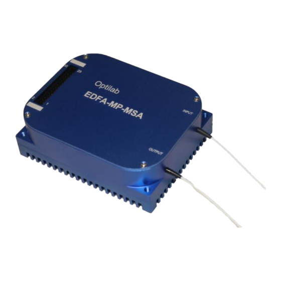
Erbium Doped Fiber Amplifier – High Power MSA Complaint Module
Caution: The user must read this manual before operating the EDFA-MP-MSA unit.
Operations other than those described in this manual may result in personal
injury and damage to the unit.
Note that any attempt to open or fix the equipment without prior approval by
Optilab, LLC. voids the warranty.
Ver. 1.6
th
January 5
, 2022
Advertisement
Table of Contents

Related Manuals for OPTILAB EDFA-MP-MSA


Summary of Contents for OPTILAB EDFA-MP-MSA
- Page 1 Optilab EDFA-MP-MSA User’s Manual Erbium Doped Fiber Amplifier – High Power MSA Complaint Module Caution: The user must read this manual before operating the EDFA-MP-MSA unit. Operations other than those described in this manual may result in personal injury and damage to the unit.
- Page 2 Copyright © 2022 by Optilab, LLC. All rights reserved. This document is copyrighted property of Optilab, LLC. It may not be used in whole or in part for manufacture, sale, or design of items without the written permission of Optilab, LLC.
-
Page 3: Table Of Contents
EDFA-MP-MSA User’s Manual Page iii of iii Table of Contents 1. GENERAL INFORMATION 1.1 I NTRODUCTION 1.2 P RODUCT VERVIEW 1.3 F EATURES 1.4 U AFETY 2. OPERATION 2.1 I NTRODUCTION 2.2 I NITIAL NSPECTION 2.3 C ONTROLS 2.4 30 P IAGRAM 2.5 O... -
Page 4: General Information
• Modular Design for OEM Integration 1.4 User Safety 1. The EDFA-MP-MSA unit emits high intensity invisible light from the optical output receptacle. Avoid direct exposure to skin and eyes. 2. The module case is fully certified for EMS protection. The user should never open the module case;... -
Page 5: Operation
Page 2 of 9 2. Operation 2.1 Introduction This chapter describes how to operate the EDFA-MP-MSA unit, and discusses the location and function of the controls and connectors. 2.2 Initial Inspection Your EDFA-MP-MSA was carefully inspected before it left the manufacturer. It should be in proper working order upon receipt. - Page 6 EDFA-MP-MSA User’s Manual Page 3 of 9 EDFA-MP-MSA – Adapter Box EATURE UNCTION This port is used to connect the power supply EDFA M ODULE ONNECTOR assembly device to the EDFA module for operation. , 30 P It is a 30 pin connector.
-
Page 7: Pin-Out Diagram
5. After checking all physical patchcord connections, turn the input signal laser source on. 6. The EDFA-MP-MSA is now enabled, with the gain current set to maximum amplification for the current input signal level. Optilab, LLC 600 E. - Page 8 EDFA-MP-MSA User’s Manual Page 5 of 9 Optical Output Adjustment Procedure To adjust the optical output level via current bias adjustment for the EDFA-MP- MSA, please refer to the PC connection mode in sections 2.6 and 2.7 for more information.
-
Page 9: Pc Connection Mode
Page 6 of 9 2.6 PC Connection Mode For the standard EDFA-MP-MSA, connecting the module to an external PC will allow for parameter monitoring and pump current adjustments. If you have an EDFA-MP-MSA with additional software control, please refer to the additional supplemental manual for complete information. -
Page 10: Troubleshooting
S: Measure optical output power with power meter and compare with readout on PC connection ‘READ’ command. Return to Optilab for repair if the difference is high (>4 dB) and cannot be corrected by cleaning or replacing the optical connectors. Always apply dust cover plugs to unused optical ports to prevent the damage of optical connectors. -
Page 11: Service And Support
4. Service and Support 4.1 Warranty Optilab, LLC guarantees its EDFA-MP-MSA unit is guaranteed to be free of defects for 1 year from the date of shipment. The guarantee does not cover any damages resulting from the misuse or improper handling of the equipment, or any incidental or consequential loss. - Page 12 EDFA-MP-MSA User’s Manual Page 9 of 9 Cleaning Optical Connector End-face with Wipe and Alcohol To properly clean optical connectors utilizing lens tissue grade wipes and alcohol follow the procedure below. The moist wipe removes dust particles, oil and contaminants that may damage or blot the end-face of the connector during connection.