Table of Contents
Advertisement
Quick Links
Optilab EDFA-PA-L-R User's Manual
Erbium Doped Fiber Amplifier – Pre-Amp Type
Rackmount
CAUTION –
USE OF CONTROLS OR ADJUSTMENTS OR PERFORMANCE OF PROCEDURES OTHER
THAN THOSE SPECIFIED HEREIN MAY RESULT IN HAZARDOUS RADIATION
EXPOSURE.
THE USER MUST READ THIS MANUAL BEFORE OPERATING THE PRODUCT.
OPERATIONS OTHER THAN THOSE DESCRIBED IN THIS MANUAL MAY RESULT IN
PERSONAL INJURY AND DAMAGE TO THE PRODUCT.
Note that any attempt to open or fix the equipment without prior approval by Optilab, LLC voids the
warranty.
Ver. 1.3
th
Jan 4
, 2021
Revision History
Advertisement
Table of Contents

Related Manuals for OPTILAB EDFA-PA-L-R


Summary of Contents for OPTILAB EDFA-PA-L-R
- Page 1 THE USER MUST READ THIS MANUAL BEFORE OPERATING THE PRODUCT. OPERATIONS OTHER THAN THOSE DESCRIBED IN THIS MANUAL MAY RESULT IN PERSONAL INJURY AND DAMAGE TO THE PRODUCT. Note that any attempt to open or fix the equipment without prior approval by Optilab, LLC voids the warranty. Ver. 1.3...
- Page 2 Copyright © 2016 by Optilab, LLC. All rights reserved. This document is copyrighted property of Optilab, LLC. It may not be used in whole or in part for manufacture, sale, or design of items without the written permission of Optilab, LLC.
-
Page 3: Table Of Contents
EDFA-PA-L-R User’s Manual Page iii of iii Table of Contents 1. General Information ___________________________________________________ 1 Introduction ______________________________________________________________ 1 Product Overview __________________________________________________________ 1 Features __________________________________________________________________ 1 User Safety _______________________________________________________________ 1 2. Operation ____________________________________________________________ 2 Introduction ______________________________________________________________ 2 Initial Inspection ___________________________________________________________ 2... -
Page 4: General Information
Rackmount Design for system integration 1.4 User Safety 1. The EDFA-PA-L-R unit emits high intensity invisible light from the optical output receptacle. Avoid direct exposure to skin and eyes. 2. The module case is fully certified for EMS protection. The user should never open the module case;... -
Page 5: Operation
Page 2 of 9 2. Operation 2.1 Introduction This chapter describes how to operate the EDFA-PA-L-R unit, and discusses the location and function of the controls and connectors. 2.2 Initial Inspection Your EDFA-PA-L-R was carefully inspected before it left the manufacturer. -
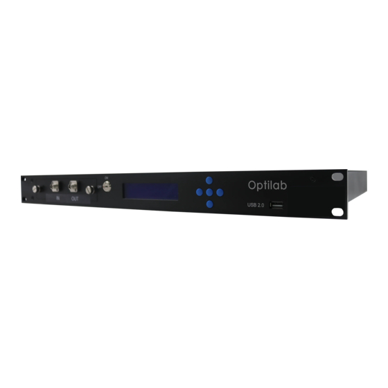
Page 6: Controls
EDFA-PA-L-R User’s Manual Page 3 of 9 2.3 Controls EDFA-PA-L-R – Front and Rear Panels Feature Function Front Panel LCD Displays the current features and functions of the rackmount EDFA system. Optical Input and The optical input and output fiber ports for the EDFA unit. -
Page 7: Operation Instructions
EDFA-PA-L-R User’s Manual Page 4 of 9 An external optical isolator at specified wavelength should be used to protect the EDFA-PA-L-R from optical feedback and to improve stability 2.4 Operation Instructions Start-up Procedure 1. After plugging in the appropriate power plug into the AC/DC Power Supply, flip the main AC switch to the On position to enable electrical power to the unit. -
Page 8: Pc Connection Mode
3. Turn the EDFA Enable Key switch back to the ON position; normal operation will resume after a few seconds. 2.5 PC Connection Mode For the standard EDFA-PA-L-R, connecting the rackmount unit to an external PC will allow for parameter monitoring and pump current adjustments. -
Page 9: Remote Command Set
EDFA-PA-L-R User’s Manual Page 6 of 9 2.6 Remote Command Set When the electrical connections have been made, and the software settings for serial port transmission are set correctly, you are now able to send commands to the LR module. -
Page 10: Troubleshooting
S: Measure optical output power with power meter and compare with readout on PC connection ‘READ’ command. Return to Optilab for repair if the difference is high (>4 dB) and cannot be corrected by cleaning or replacing the optical connectors. Always apply dust cover plugs to unused optical ports to prevent the damage of optical connectors. -
Page 11: Warranty
Page 8 of 9 4.1 Warranty Optilab, LLC guarantees its EDFA-PA-L-R unit is guaranteed to be free of defects for 1 year from the date of shipment. The guarantee does not cover any damages resulting from the misuse or improper handling of the equipment, or any incidental or consequential loss. - Page 12 EDFA-PA-L-R User’s Manual Page 9 of 9 should use only industrial grade 99% pure isopropyl alcohol and follow the procedures below to keep the connectors, adaptors and receptacles clean. Cleaning Optical Connector End-face with Wipe and Alcohol To properly clean optical connectors utilizing lens tissue grade wipes and alcohol follow the procedure below.