
Related Manuals for ACU-RITE VUE


Summary of Contents for ACU-RITE VUE
- Page 1 VUE R EADOUTS SALES & SERVICE: A Tech Authority, Inc. 13745 Stockton Ave. Chino CA 91710 909-614-4522 sales@atechauthority.com REFERENCE MANUAL...
- Page 3 VUE Key Layout Display Aera Soft keys Page Indicator light UP/DOWN arrow keys are also used to adjust the screen contrast Axis Keys Numeric Keypad ENTER key CLEAR key Hard function keys VUE Soft keys There are two pages of soft key functions to select from the operating modes.
- Page 4 Soft Key function Soft key Press when ready to identify a reference mark (see "ENABLE/DISABLE REF function" on page Opens the Tool Table. See "Tool Table" on page 8 for Milling. See "Tool Table" on page 22 for Turning. The tool key is a soft key for the one axis readout only.
- Page 5 Readout Parameter Access Code An access code must be entered before machine-related installation parameters can be set or changed. This prevents inadvertent adjustments to the installation setup parameters. IMPORTANT! The access code is 8891. Access to Machine Parameter Operations Refer to the Setup section also. Begin by pressing the SETUP soft key.
-
Page 7: Introduction
Operations, Mill Specific Operations and Turn Specific Operations. DRO axis availability. The VUE DRO is available in one, two, and three axis form. The 3 axis VUE DRO is used through out this manual for illustration and description of function keys. - Page 8 viii...
-
Page 9: Hassle-Free Warranty
ACU-RITE is proud to offer the 3-Year Hassle-Free Warranty for all digital readout systems, vision readout systems, and precision glass scales. This warranty will cover all of the ACU-RITE repair and replacement costs for any readout or precision glass scale returned during the three (3) year warranty period. ACU-RITE will repair or replace the damaged components - regardless of the product’s condition absolutely free, no questions asked. -
Page 11: Table Of Contents
VUE Axis availability ....................vii Symbols within Notes..................... vii VUE Fonts....................... vii Hassle-Free Warranty Warranty ........................ix I – 1 Introduction to VUE Layout of Screen...................... 1 VUE Hard Keys ......................2 Operating Modes ..................... 3 Reference Mark Evaluation..................3 Working without reference mark evaluation............4 ENABLE/DISABLE REF function................. - Page 12 I – 2 Milling Specific Operations Key Functions Detailed .................... 8 Tool Hard Key ..................... 8 Tool Table ......................8 Tool Compensation..................... 8 Δ Sign for the length difference L................ 9 Calling the Tool from the Tool Table ..............9 Datum Setting....................
- Page 13 II – 1 Installation Setup Installation Setup Parameters ................29 Encoder Setup ....................... 29 Display Configuration ..................... 30 Coupling ......................... 30 Z Coupling (turning applications only) ..............31 Enabling Z Coupling ..................31 Disabling Z Coupling ..................31 Error Compensation ....................32 Linear Error Compensation ................
-
Page 15: I - 1 Introduction To Vue
11 Soft key Labels 12 Display Area 13 Near Zero Warning (In Distance-To-Go mode only) ACU-RITE’s VUE readout provides application-specific features that allows the most productivity from a manual machine tool. Status Bar - This displays the current datum tool, feed rate, job clock time, unit of measure, operating mode status, page indicator, and set/zero. -
Page 16: Vue Hard Keys
A two, or three axis readout will have all the hard keys shown below. The last two keys are specific to a VUE readout that is either for milling, or turning. The first symbol applies to a milling readout, and the second symbol applies to a turning readout. -
Page 17: Operating Modes
If the VUE is configured for turning, all tool offsets are used in both the absolute, and incremental modes. Press the ABS/INC hard key to toggle between these two modes. -
Page 18: Working Without Reference Mark Evaluation
Working without reference mark evaluation The VUE can also be used without crossing over the reference marks. Press the NO REF soft key to exit the reference mark evaluation routine, and continue. The reference marks can still be crossed over at a later time if it becomes necessary to define a datum that can be re-established after a power interruption. -
Page 19: Job Setup Parameters
Job Setup Parameters To view, and change Job Setup parameters, first press the SETUP soft key. Use the UP/DOWN arrow keys to highlight the parameters of interest. press the Enter key. Units The Units form is used to specify the preferred display units, and format. -
Page 20: Diameter Axes
Diameter Axes Select Diameter Axes to set which axes can be displayed in either radius, or diameter values. ON indicates that the axis position will be displayed as a diameter value. When OFF, the Radius/Diameter feature does not apply. for turning applications see page 27 for the Radius/Diameter feature. -
Page 21: Console Adjustment
Set, and Zero. The current state is indicated in the Status Bar. When the state is Set, and the VUE is in Actual Value mode, selecting an Axis key opens the Datum form for the selected axis. If the VUE is in Distance-To-Go mode, a Preset form opens. -
Page 22: I - 2 Milling Specific Operations
(R+), or shortened (R–) by the value of the tool radius. for more information see "Presets" on page 12. The length offset may be entered as a known value, or the VUE may determine the offset automatically. The tool length is the difference in Δ... -
Page 23: Sign For The Length Difference L
If the tool is shorter than the reference tool: L < 0 (–). As indicated above it is also possible to have the VUE determine a tool’s length offset. This method involves touching the tip of each tool to a common reference surface. This allows the VUE to determine the difference between the length of each tool. -
Page 24: Datum Setting
Datum settings define the relationships between the axis positions, and the display values. Setting datum points can be done by using the VUE probing functions with a tool. Datum points are set by touching the edges of the workpiece, one after the other with a tool, and manually entering the tool positions as datum points. -
Page 25: Datum Setting With A Tool
Datum Setting with a Tool Using a tool to set datum points can still use the VUE probing functions. The following probing soft key functions are available: Workpiece edge as datum: EDGE soft key Centerline between two workpiece edges: CENTER LINE soft key. -
Page 26: Presets
Presets The Preset function allows the operator to indicate the nominal (target) position for the next move. Once the new nominal position information is entered the display will switch to Distance-To-Go mode, and show the distance between the current position, and the nominal position. -
Page 27: Preparation
Preparation: Select the tool with the appropriate tool data. Pre-position the tool to an appropriate location (such as X = Y = -1”). Move the tool to milling depth. Press the SET/ZERO soft key so that the DRO is still in Set mode. Press the Y axis key. -
Page 28: Incremental Distance Preset
Incremental Distance Preset Example: Drilling by traversing to display value zero with incremental positioning. Enter the coordinates in incremental dimensions. These are indicated in the following (and, on the screen) with a preceding I (Incremental). The datum is the workpiece zero. -
Page 29: 1/2 Hard Key
This section describes the hole pattern functions for Circle, and Linear patterns. Press the CIRCLE PATTERN, or LINEAR PATTERN hard key to access the Pattern function then enter the required data. VUE then calculates the positions of all the holes, and displays the pattern graphically on the screen. -
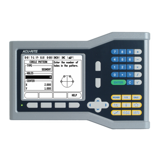
Page 30: Circle Pattern
Circle pattern Example: Enter data, and execute a circle pattern. Holes (no. of): 4 Coordinates of center: X = 2.0” / Y = 1.5” Bolt circle radius: 5 Start angle: Angle between X axis, and first hole: 25° Hole depth: Z = -0.25” 1st step: Enter data Press CIRCLE PATTERN hard key. -
Page 31: Linear Pattern
Linear Pattern Information required: Linear pattern type (array, or frame) First hole (1st hole of the pattern) Holes per row (number of holes in each row of pattern) Hole spacing (the spacing, or offset between each hole in the row) Angle (the angle, or rotation of the pattern) Depth (the target depth for drilling in the tool axis) Number of rows (number of rows in the pattern) -
Page 32: Incline Milling
Incline Milling Entry Form: The Incline Milling form is used to specify the flat surface to be milled. Press the INCLINE MILLING hard key to open the form Plane - Select the plane by pressing the PLANE soft key. The current selection is shown on the soft key, and in the plane field. - Page 33 When executing a surface milling operation, three views are available: incremental DRO, contour, and absolute DRO. Press the VIEW soft key to toggle through the available screens. The contour view shows the position of the tool relative to the milling surface. When the crosshair representing the tool is on the line representing the surface, the tool is in position.
-
Page 34: Arc Milling
Arc Milling Entry Form: The Arc Milling form is used to specify a curved surface to be milled. Press the ARC milling hard key to open the form. Plane Selection: Select the plane by pressing the PLANE soft key. The current selection is shown on the soft key, and in the plane field. - Page 35 When executing a surface milling operation, three views are available: incremental DRO, contour, and absolute DRO. Press the VIEW soft key to toggle through the available screens. The contour view shows the position of the tool relative to the milling surface. When the crosshair representing the tool is on the line representing the surface, the tool is in position.
-
Page 36: I - 3 Turning Specific Operations
Select the X axis key. Enter the position of the tool tip, for example, X= .100. Remember to ensure the VUE is in diameter display mode (Ø) if a diameter value is used. Touch the workpiece face with the tool. -
Page 37: Setting Tool Offsets With Lock Axis Function
Turn the spindle off, and measure the workpiece diameter. Enter the measured diameter, or radius, and press ENTER. Remember to ensure the VUE is in diameter display mode (Ø). Calling a Tool from the Tool Table To call a tool, press the TOOL hard key. -
Page 38: Datum Setting
Touch the workpiece at point 1. Enter the radius, or diameter of the workpiece at that point. Remember to ensure the VUE is in diameter display mode (Ø) if a diameter value is used. Press the DOWN ARROW key to advance to the Z axis. -
Page 39: Setting Datums Using Lock Axis Function
Setting Datums using LOCK AXIS Function The Lock Axis function is useful for setting a datum when a tool is under load, and the diameter of the workpiece is not known. To use the Lock Axis function: Press the DATUM hard key. The Cursor will be in the Datum Number field. -
Page 40: Taper Calculator Hard Key
Taper Calculator Hard Key Use the taper calculator to caculate taper angle. Calculate tapers either by entering dimensions from a print, or by touching a tapered workpiece with a tool, or indicator. Entry values: for the taper ratio, calculation requires: Length of the taper Change in the radius of the taper. -
Page 41: Presets
(available in both operating modes). RADIUS/DIAMETER Soft Key Drawings for lathe parts usually give diameter values. VUE can display either the radius, or the diameter. When the diameter is being displayed, the diameter symbol (Ø) is shown next to the position value. -
Page 42: Vectoring
Vectoring Vectoring breaks down the movement of the compound axis into the crossfeed, or longitudinal axes. When turning threads for example, vectoring provides the diameter of the thread in the X-axis display, even though the cutting tool is moving with the compound axis handwheel. -
Page 43: Ii - 1 Installation Setup
II – 1 Installation Setup Installation Setup Parameters Installation Setup is accessed by pressing the SETUP soft key, which brings up INSTALL. SETUP soft key. Installation Setup parameters are established during the initial installation, and most likely, will not often change. For this reason, the installation setup parameters are protected by the passcode. -
Page 44: Display Configuration
In the Error Monitor field, select whether the system will monitor, and display encoder errors by selecting ON, or OFF. When an error message occurs, press the C key to remove it. The encoder resolution and count direction can also be established by just moving each axis. -
Page 45: Z Coupling (Turning Applications Only)
Z Coupling (turning applications only) The VUE Turning application provides a quick method for coupling the Z0, and Z axis position on a 3 axis system. The display can be coupled in either the Z, or Z0 displays. Enabling Z Coupling To couple the Z0, and Z axis, and have the result displayed on the Z0 display, press and hold the Z0 key approximately 2 seconds. -
Page 46: Error Compensation
The VUE provides the opportunity to compensate for these errors, and each axis can be programmed separately with the appropriate compensation. -
Page 47: Non-Linear Error Compensation
The required correction values are calculated and entered in a table. VUE supports up to 200 points per axis. The error value between two entered adjacent correction points is calculated with linear interpolation. -
Page 48: Viewing The Compensation Table
Viewing the Compensation Table Press the EDIT TABLE soft key. To switch between the table and graph views, press the VIEW soft key. Press the Up or Down arrow keys or the numeric keys to move the cursor within the table. The error compensation table data may be saved to or loaded from a PC via the USB port. -
Page 49: Counter Settings
Counter Settings The Counter Settings feature is the parameter where the operator defines the user application for the readout. The choices are for milling or turning applications. A FACTORY DEFAULT soft key appears in the Counter Settings choice of options. When pressed, the configuration parameters (based on either mill or turn) will be reset to factory defaults. -
Page 50: Installation And Electrical Connections
II – 2 Installation and Electrical Connections Installation The DRO is mounted to a tilt/swivel feature: See "Dimensions" on page Electrical requirements Voltage 100 - 240 Vac Power 25 VA max. Frequency 50/60 Hz (+/- 3Hz) Degree of protection (EN 60529) IP 40 back panel IP 54 front panel Fuse 500 mA/250 Vac, 5 mm x 20 mm, Slo-Blo (line and neutral fused) Environmental... -
Page 51: Ii - 3 Dimensions
II – 3 Dimensions Overview Dimensions in inches/mm Top view with Dimensions Back view Front view with Dimensions Accessory ID Number ID Number Accessory 627052-01 Pkgd, Mounting Base... - Page 52 M8 Lock nut (included with DRO) Tilt / Swivel Feature (included with DRO) Read out mounting arm options (not included) Handle (included with DRO) M8 x 70mm Mounting bolt (included with DRO) The DRO mounting base incorporates a slot feature that prevents the lock nut from turning.
- Page 53 DRO mounting with arm (reference information) M8 x 20 mm Hex Head Mounting base op- Screw (included with tion accessory (not Mounting base option) included with DRO) Tilt / Swivel Feature (included with DRO) M8 Tightening handle (included with Mounting base option) DRO mounting with base...
- Page 55 Numerics 1/2 Hard Key ... 15 Edge soft key ... 11 Milling Specific Operations and Soft Key Coupling ... 30 Electrical Requirements ... 36 Functions Detailed ... 8 Enable Ref soft key ... 4 Mirror ... 5 Enable/Disable Ref function ... 4 Absolute Distance Preset ...
- Page 56 Tool setting, turning ... 22 Tool soft key (Turning) ... 22 Units ... 5 Units of measurement, setting ... 5 Up/Down arrow keys ... iii Vectoring ... 28 Viewing the Compensation Table ... 34 VUE Hard Keys ... 2 Z Coupling ... 31...
- Page 58 A Tech Authority, Inc. CERTIFIED One Precision Way 13745 Stockton Ave. Jamestown, NY 14701 MANUFACTURER Chino CA 91710 (716) 661-1700 909-614-4522 (716) 661-1888 sales@atechauthority.com e-mail: sales@acu-rite.com www.acu-rite.com Ve 01 606085-20 8/09 Printed in USA Subject to change without notice • • •...
Need help?
Do you have a question about the VUE and is the answer not in the manual?
Questions and answers