
Subscribe to Our Youtube Channel
Related Manuals for S.P.E. ChargePlus Flex


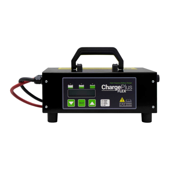
Summary of Contents for S.P.E. ChargePlus Flex
- Page 1 High Frequency Battery Charger Model #: 24-CBHF2M-3625FLEX Attention: Read the user manual carefully before using the battery charger. User Manual Important Safety, Installation, and Operation Instructions...
-
Page 2: General Warnings
IMPORTANT SAFETY INSTRUCTIONS. KEEP THESE INSTRUCTIONS. This manual contains important instructions for the safety of the user and operation of the device. GENERAL WARNINGS 1) Before each use of the battery charger the instructions set out below must be carefully read and abided by. 2) The failure to follow these instructions and/or errors in installing or using the battery charger could lead to endangering the operator and/or damaging the device, voiding the manufacturer's guarantee. - Page 3 9) Do not use the battery charger outdoors. 10) Do not expose the battery charger to rain, water splashes or steam. 11) Do not install the battery charger in caravans and / or similar vehicles. 12) Do not install the battery charger near any heat sources or in areas with high concentrations of dust.
- Page 4 23) The battery charger tolerance thresholds, as far as levels of over-voltage and overcharging are concerned, are used only for the safeguarding of the systems of the same and have no safety functions for the battery itself, the safety of which depends solely on the BMS, even when the battery charger is connected to the battery, whether the latter is being charged or not.
- Page 5 be protected by an electrical device by law (fuse and/or automatic cut- out), capable of absorbing an electrical current equaling the absorption of current stated on the matriculation number of the battery charger, increased by 10%. 32) Do not open the battery charger as there are no parts which can be serviced and/or replaced by the user.
- Page 6 Battery type = 80 – 280Ah C5 (130 – 350Ah C20) LEAD-ACID, GEL, AGM, LITHIUM Number of cells = 6 – 12 – 18 – 24 Storage temperature: from -20°C to +50°C (from -4°F to 122°F) Relative humidity: 0 – 80% up to 50°C (0 - 80% up to 122°F) Operating temperature: from 0°C to 45°C (from 32°F to 113°F) Programmable Charging Profiles are: INDEX...
- Page 7 BATTERY CHARGER IDENTIFICATION LABEL MODEL BATTERY CHARGER SERIAL CUSTOMER PART NUMBER NUMBER BATTERY CHARGER PART NUMBER MANUFACTURE DATE MODEL INPUT VOLTAGE INPUT VOLTAGE AND MAINS ABSORPTION OUTPUT VOLTAGE AND CURRENT OUTPUT VOLTAGE AND CURRENT MAIN FUSE VALUE BATTERY TYPE - NUMBER OF CELLS CHARGING CURVE SETTING H MAINS ABSORPTION...
-
Page 8: Wall Mount Installation
WALL - MOUNT INSTALLATION WALL Drill two or four holes into the wall and fasten charger with 2 or 4 screws. Do not tighten the screws all the way so that the charger can hang on the screws. Maximum height 150cm (59 1/16") Minimum height 30cm (11 13/16") FLOOR ELECTRONIC BATTERY CHARGER - OPERATING MANUAL... - Page 9 On the next screen, the LCD will display the parameters for: • Battery voltage 36V 25A • Charging current et 12h • Number and type of charging curve A test is conducted on the battery voltage to decide whether or not to start the charging process.
-
Page 10: Charging Settings
If the test is successful, the battery charger displays the battery voltage before starting the charge, then displays the current value (A), the voltage (V), Recharged Capacity (C) and Time Elapsed from the start (t) Indicating that the charging is in progress by turning on the red LED. Shown below is an example of what the battery charger display looks like after a successful start: The progress of the charging cycle... - Page 11 You can now use the keys to scroll through the various parameters. The following parameters can be changed: Type of curve, Voltage, and Current. After selecting the parameter, you want to change, press to activate SELECT the option to edit the value (indicated by the red DL3 LED that turns on) and use the and keys to set the desired value.
-
Page 12: Error Messages On The Display
LED MESSAGES DISPLAYED Ref. Messages reported DL3 LED DL2 LED DL1 LED (Red) (Yellow) (Green) Start Auto-start execution Phase 1: Initial charge at constant current ON Phase 2: Final charge at constant voltage F3_I (*) Phase 3: Final charge at constant current F3_U (*) Phase 3: Final charge at constant voltage Charging complete... - Page 13 REF. MESSAGES REPORTED DL3 LED DL2 LED DL1 LED (Red) (Yellow) (Green) Phase timeout or too much current No Battery Inversion of polarity Battery in Short Circuit Incorrect Battery Voltage Over temperature error Corrupted charging profile Shown is an example of how an “E02: Temperature” error will be displayed.
- Page 15 In case you need help with S.P.E.’s chargers you already have and use – like technical assistance, repairs due to faults or replacements, contact: Flight Systems Industrial Products (FSIP) 1015 HARRISBURG PIKE – CARLISLE, PA 17013 WEBSITE: www.shop.fsip.biz | PHONE: 1-800-333-1194 Flight Systems Industrial Products (FSIP) MIDWEST BRANCH 80 S.
- Page 16 NOTES/COMMENTS:...
Need help?
Do you have a question about the ChargePlus Flex and is the answer not in the manual?
Questions and answers