Advertisement
STI LATCHING/TIMER MODEL LT-1
NOTE:
It is important to read, understand and follow all instructions provided with this
product. It is the installer's responsibility to comply with NFPA 70, 72 & 101, NEC,
mounting specifications according to ADA and other applicable codes. This product is
not to be used in place of panic hardware. To avoid electrical shock, DO NOT attempt
to install this product when power is on. After installation and testing are complete,
provide a copy of this manual to all personnel responsible for testing and maintenance
of this product.
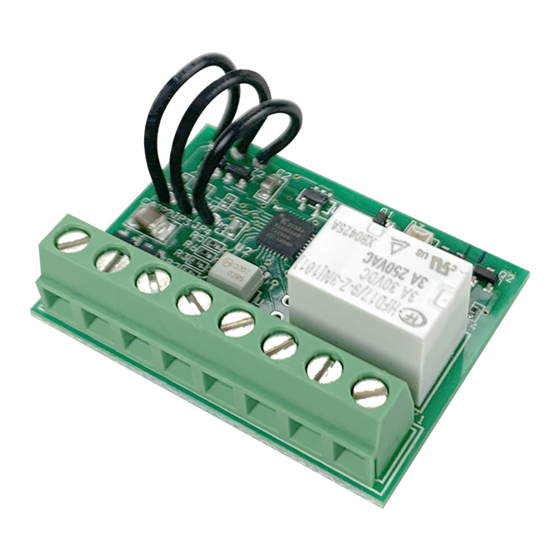
1.28 in.
33mm
.632 in.
16mm
*POWER IN
12 - 24 VAC/VDC, 18 mA
TIMER
INPUT COM
CONTROL
FORM "C"
DRY CONTACTS
3A, 30VDC
1.74 in.
44mm
+
-
RESET
TRIGGER
N.C.
COM
N.O.
POWER LED GREEN
RELAY ACTIVE LED RED
Advertisement
Table of Contents

Related Manuals for STI LT-1


Summary of Contents for STI LT-1
- Page 1 STI LATCHING/TIMER MODEL LT-1 NOTE: It is important to read, understand and follow all instructions provided with this product. It is the installer’s responsibility to comply with NFPA 70, 72 & 101, NEC, mounting specifications according to ADA and other applicable codes. This product is not to be used in place of panic hardware.
- Page 2 If the trigger is activated during a timing cycle, the timer is restarted. NOTE: To ensure jumpers do not reattach or short to other components, cut jumper off completely flush to PCB. Electronic warranty form at www.sti-usa.com/wc14. TIMER OVERRIDE *POWER IN...
Need help?
Do you have a question about the LT-1 and is the answer not in the manual?
Questions and answers