Table of Contents
Advertisement
Quick Links
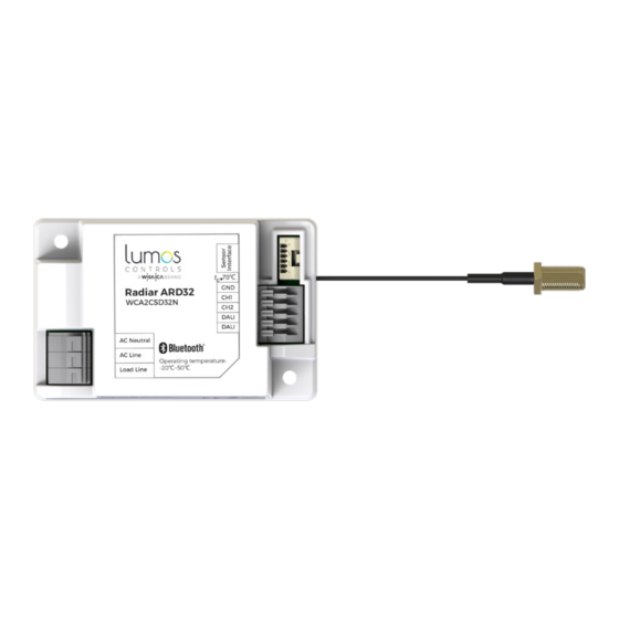
Radiar ARD32
32 Slave DALI Room Controller
CE, RoHS 2.0, REACH, WEEE
INSTALLATION AND QUICK START SHEET
WARNING AND GUIDELINES!!!
Read and follow all safety instructions!!
DO NOT INSTALL DAMAGED PRODUCT! This product has been properly packed so that
no parts should have been damaged during transit. Inspect to confirm. Any part
damaged or broken during or after assembly should be replaced.
WARNING : TURN THE POWER OFF AT THE CIRCUIT
BREAKER BEFORE WIRING
WARNING: Risk of Product Damage
Electrostatic Discharge (ESD): ESD can damage product(s). Personal grounding
equipment should be worn during all installation or servicing of the unit
Do not stretch or use cable sets that are too short or are of insufficient length
Do not modify the product
Do not mount near gas or electric heater
Do not change or alter internal wiring or installation circuitry
Do not use product for anything other than its intended use
WARNING - Risk of Electric Shock
Verify that supply voltage is correct by comparing it with the product
information
Make all electrical and grounded connections in accordance with the National
Electrical Code (NEC) and any applicable local code requirements
All wiring connections should be capped with UL approved recognized wire
connectors
All unused wiring must be capped
Product Overview
Radiar ARD32 is a DALI room controller which can be connected to a maximum of 32
DALI LED drivers. It is a part of the Lumos Controls ecosystem, including controllers,
sensors, switches, modules, drivers, gateways, and analytical dashboards.
INSTALLATION INSTRUCTIONS
using an IP68 box
Radiar ARD32 room controllers can be packed within an IP rated junction box to install
in the wet locations
Open the IP68 enclosure and remove the connectors and locknut using screw driver
Take the electrical wire of 18AWG and cut in to 4 pcs (8-10cm) for AC line, Neutral, DALI+,
DALI- respectively
Insert one end of the wires into the 221-412 series Wago connector
Connect the other end of the wire in to the device connector (AC line, Neutral, DALI+,
DALI-) respectively
Connect the 130mm wire antenna into the antenna connector
Paste the double-sided tape on the backside of the device and fix it within the enclosure
Remove the grommet from the connector-1 and insert the AC line, Neutral wires from the
mains into the enclosure. Now connect the connector with the enclosure using the locknut
Connect the Line and Neutral wires from the mains with the Line and Neutral wires of the
DALI controller using the Wago connectors to power the controller
Insert the DALI+ and DALI- from the drivers into the enclosure through the connectors
and connect it with the DALI+ and DALI- of the device using Wago connectors to control
the driver. Once the wires are in, tighten the connector with lock nut
Take out the 130mm wire antenna from the enclosure via the connector for better
communication. Similarly connect the AC input lines with the controllers to power it
Cover the enclosure with the face plate /lid using screws
Do's
Installation should be performed by a
qualified electrician
Installation shall be in accordance with
all applicable local and NEC codes
Turn the power OFF at circuit breakers
before wiring
Observe the correct polarity of output
terminal
Specifications
Min
Input Voltage
100
Input Current
_
External Relay Input
_
Power Consumption
_
Protection Class
_
Built in Class II
Sensor Interface
0-3.3V digital input /UART
Surge Transient
_
Protection
Dimming Output 1 & 2
0
Dimming Range
0
Dimming Resolution
_
Operating Temperature
-20
Dimensions
_
70.9×45.4×26.1
Dimensions
_
2.8×1.8×1.0
Case Temperature
_
Required tools & supplies
Wago connector
Screwdriver
1
Connect the wire antenna onto the antenna connector in the device
2
Open the box and fix the device into it using a double-sided tape
Dont's
Don't use outdoors
Avoid input voltage exceeding
maximum rating
Don't dissemble the products
-
Type
Max
Unit
Remarks
_
277
VAC
Rated Input Voltage
10
30
mA
@max RF transmitting
Input for AC
_
0.8A
_
relay @ 230VAC
1.0
3
W
Active power
Suitable for class I
_
_
and class II luminaires
_
_
_
2
kV
@Line to Line:
Bi-Wave
_
10
V
Max output
tolerance ±0.5V
_
100
%
_
7
_
bit
100 steps
_
50
ºC
_
_
mm
L x W x H
_
in
L
_
70
ºC
_
Double sided
Electrical wires
Screws
electrical tape
x W x H
Advertisement
Table of Contents

Related Manuals for WiSilica Lumos Controls ARD32


Summary of Contents for WiSilica Lumos Controls ARD32
- Page 1 Radiar ARD32 32 Slave DALI Room Controller CE, RoHS 2.0, REACH, WEEE INSTALLATION AND QUICK START SHEET Do’s Dont's Installation should be performed by a Don't use outdoors qualified electrician WARNING AND GUIDELINES!!! Installation shall be in accordance with Avoid input voltage exceeding Read and follow all safety instructions!! all applicable local and NEC codes maximum rating...
- Page 2 Take in the DALI wires from the driver Take in the AC wires from the Mains Cover the box with using screws Fix this box onto a flat surface through the connector on the box and through a connector (in the box) and connect them to the DALI push-in connect to the AC Line(Brown) and AC connectors on the device.
- Page 3 Fuse has blown Inappropriate wiring Warranty 5-year limited warranty Please find warranty terms and conditions Note: Specifications may change without notice Actual performance can vary due to end-user environment and application +1 949-397-9330 All Rights Reserved WiSilica Inc Ver 1.0 Mar 2022...
Need help?
Do you have a question about the Lumos Controls ARD32 and is the answer not in the manual?
Questions and answers