
Related Manuals for ADEMCO VISTA Series


Summary of Contents for ADEMCO VISTA Series
- Page 1 VIST VIST A 10 UK A 10 UK VIST A 10 UK A 10 UK VIST VIST A 10 UK ENGINEER’S ENGINEER’S ENGINEER’S ENGINEER’S ENGINEER’S MANU MANU MANU AL MANU MANU www.PDF-Zoo.com firealarmresources.com...
- Page 2 www.PDF-Zoo.com firealarmresources.com...
-
Page 3: Table Of Contents
Contents SECTION 1: SAFETY INSTRUCTIONS ........... 5 General ....................5 Siting ....................... 5 Fixing ...................... 5 Ventilation ....................5 Cabling ....................6 Mains Supply Connections ..............6 Cable Type ..................... 7 Fuses ......................7 Equipment Rating ................. 7 Batteries ....................7 Saftey Statement .................. - Page 4 1. Reset ......................23 2. Bypassing (Isolating) Zones ................. 23 3. User Codes ....................23 4. View Event Log .................... 23 5. Set Real Time Clock ..................23 6. Communication Test ..................23 7. Troubleshooting.................... 24 ADEMCO LIMITED WARRANTY ........25 www.PDF-Zoo.com firealarmresources.com...
-
Page 5: Section 1: Safety Instructions
SECTION 1: SAFETY INSTRUCTIONS Please read this section carefully General It is essential that this product is installed correctly, in particular with respect to persons safety, connection of the mains electricity supply, and connection to the Public Switched Telephone Network (PSTN). This product is not suitable for installation, maintenance or connection by the user. -
Page 6: Cabling
Cabling The product has high voltage barriers between the mains supply (excessive voltage), the alarm wiring terminals (safe extra low voltage), and the telephone line terminals (Telecom network voltage). Each control is individually tested before it leaves the factory to ensure the integrity of these barriers. It is essential that these barriers are maintained in the way the cables enter the cabinet, are routed inside the cabinet, and routed externally. -
Page 7: Cable Type
The insulation of each conductor must be prepared and connected such that no part of the bare conductor is visible or protruding outside the terminal block, and in the case of standard conductors, that all the strands are twisted together and firmly clamped in the terminal. -
Page 8: Saftey Statement
Saftey Statement Terminals marked Excessive Voltage are for connection for 240V AC 50Hz mains supply only. Terminals marked SELV (Safety Extra Low Voltage) are for connection to other devices in the alarm system only. Terminals marked TNV (Telephone Network Voltage) are for connection to the PSTN via an NTE5 Master Socket only. -
Page 9: Section 2: Installing The Vista 10
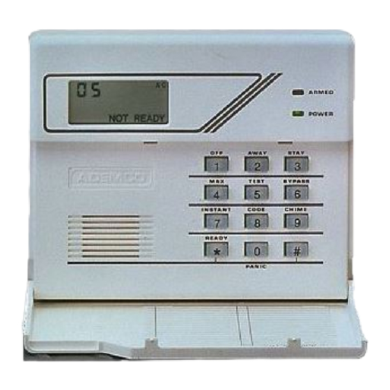
SECTION 2: INSTALLING THE VISTA 10 Installation Procedure 1. Install the Vista control panel in accordance with the safety instructions. A keyhole slot is provided for the top fixing; it is not necessary to remove the circuit board. 2. Fit and connect the main remote keypad, as shown in Figure 2.1 PCB Connections. -
Page 10: Summary Of Main Pcb Connections
Summary of Main PCB Connections Battery / Ground Terminals Equipment Ground Terminal - connection must be intact at all times. BATT- Battery Negative - Connect to the -ve (black) terminal of the battery. BATT+ Battery Positive - Connect to the +ve (red) terminal of the battery. Output Triggers (Terminal PLA) Fire trigger Panic trigger... - Page 11 Telephone Line Terminals (Terminal PLF) These connections are for connection to a NTE5 masterplan line box. See Telephone Line Wiring Note: (a) ZONE 9 is used for external bell tamper and the lid tamper switch. ZONE 7 alarm loop may be programmed for push-to-set or keyswitch setting.
-
Page 12: Communication
Besides reporting an alarm, a restore report may also be sent for each channel. In Ademco contact ID format, the channels must be assigned in the same manner but the message sent to the receiver is not sent as a channel, but as a unique message type. -
Page 13: Telephone Line Wiring
the main PCB is off. Do not attempt to continue if mains supply is still present within the control. Remove the battery from the cabinet after disconnecting its leads. Telephone Line Wiring A connection is provided on the Vista 10 UK for an ex-directory standard PSTN telephone line. -
Page 14: Ren
The REN is a guide to the customer as to the maximum number of items of apparatus which may be connected simultaneously to the telephone line. The total REN is obtained by adding up the REN values of each of the items of apparatus connected to the exclusive line. - Page 15 Figure 2.2 Telephone Line Connections www.PDF-Zoo.com firealarmresources.com...
- Page 16 www.PDF-Zoo.com firealarmresources.com...
-
Page 17: Section 3: Programming The Vista 10
SECTION 3: PROGRAMMING THE VISTA 10 General When access has been made to program mode, the system parameters can be changed from the factory default settings. The default values for each of the parameters are shown in brackets above each programming field. If no changes are made to these defaults the system will operate as an audible only alarm. -
Page 18: Programming Fields
Programming Fields Entry/Exit (0 3) Ö/# 09 Entry Time Multiples of 10 Seconds i.e. 01=10 secs, 02=20secs etc. Area 1 Multiples of 10 Seconds (0 3) Ö/# 10 Exit Delay i.e. 01=10 secs, 02=20secs etc. 00 = Final Contact Set Area 1 Ö/# 17 Supplementary Entry 0 = NO... -
Page 19: Engineer
Ö/# 16 Strobe to Confirm Away Set 0 = NO 1 = YES Ö/# 28 Programme Tamper or 0 = Program Tamper Alarm Abort Trigger 1 = Alarm Abort Trigger Ö/# 47 Tamper or Set Latch Trigger 0 = Tamper trigger output 1 = Set Latch trigger output Ö/# 50 Fire or Open/Close Trigger 0 = Fire... -
Page 20: Communication
(1 5) (1 5) (1 5) Ö/# 90 Secondary Account Number Ö/# 46 Digicom Format 0 = Ademco Contact ID 1 = High Speed (8 channel) Ö/# 49 Checksum Verification 0 = No 1 = Yes (only used on ADEMCO receivers) www.PDF-Zoo.com... - Page 21 Ö/# 51 Dual Reporting 0 = No (reports to Primary No.) 1 = Yes (reports to both Primary and Secondary telephone No.s) Ö/# 53 Send Restore on 1st code 0 = No (second code + off) + off 1 = Yes Affects both Digicom and Redcare triggers (only affects Digi if using High Speed format;...
-
Page 22: Downloading
Downloading If the system is to be programmed from NEW by the downloading computer, the following procedure should be used: 1. Enter Program Mode by typing the engineer code + 2. Enter Ö to load the system defaults. 3. Enter Ö and enter the telephone number of the downloading computer. -
Page 23: Section 4: Installation/Service Notes
SECTION 4: INSTALLATION/ SERVICE NOTES 1. Reset In ALARM condition your reset options are: Customer, Engineer or *Technistore (selected in field 24). In a daytime TAMPER condition your reset options are: Cus- tomer or Engineer. (selected in field 23). In addition the system may be reset from the DOWNLOAD computer. -
Page 24: Troubleshooting
7. Troubleshooting CHECK = Indicates tampering to the zone displayed. NO AC = You have lost mains power BAT = Battery is running low. OC = indicates control is not communicating with the panel. CE = Call Engineer CD = Fault with the Telco line or see field 22 CF = Comms failure to the C/S CS = Checksum error (Load defaults advised) www.PDF-Zoo.com... -
Page 25: Ademco Limited Warranty
18 months from the date stamp control on the product or, for products not having an Ademco date stamp, for 12 months from date of original purchase unless the installation instructions or catalogue sets forth a shorter period, in which case the shorter period shall apply. - Page 26 www.PDF-Zoo.com firealarmresources.com...
- Page 27 www.PDF-Zoo.com firealarmresources.com...
- Page 28 IE1-4110 (ISSUE A) 30/7/99 www.PDF-Zoo.com firealarmresources.com...
Need help?
Do you have a question about the VISTA Series and is the answer not in the manual?
Questions and answers