Advertisement
Quick Links
Advertisement

Related Manuals for Conrad QU-CM-5510/-2


Summary of Contents for Conrad QU-CM-5510/-2
- Page 1 USER MANUAL QU-CM-5510/-2 QU-CM-5510/-2 MOTORIZEDCARD READER MODULE Page 1 of 9...
- Page 2 Support any two of the three types SIM card encryption Support all the three types Or any two with QU-CM-5510/-2- C SIM card encryption Support all the three types with SIM card encryption QU-CM-5510/-2- D ※ R&W: Read & Write...
- Page 3 USER MANUAL QU-CM-5510/-2 Ⅱ . FEATURES & SPECIFICATIONS Subject Specification Magnetic card Reading Accordance with ISO7810 7811 standard card EMV、7816 PBOC 3.0 IC card Reading & Writing S50、S70、 ID card RF card Reading & Writing SIM card operation 8 SIM card ports...
- Page 4 USER MANUAL QU-CM-5510/-2 Ⅳ .INTERFACE EXPLANATION AND CONNECTION NOTE: TO AVOID sudden high power damage, please do connect the communication wire before connect the Power cable. 4 PIN 3 PIN 3 PIN Communication Interface RS232 4 PIN DC12V POWER Interface...
-
Page 5: Power Supply Interface
USER MANUAL QU-CM-5510/-2 Power supply interface POWER CABEL TO MACHINE TO DC12V POWER SOCKET POWER POWER-ZIP PIN-NO. INPUT REQUIREMENT PIN 2&3 ) ( Connect with Ground Black Wire DC12V Current over 1.5A ( PIN 1&4 ) Red Wire Power cable connector ±... - Page 6 USER MANUAL QU-CM-5510/-2 Page 5 of 9...
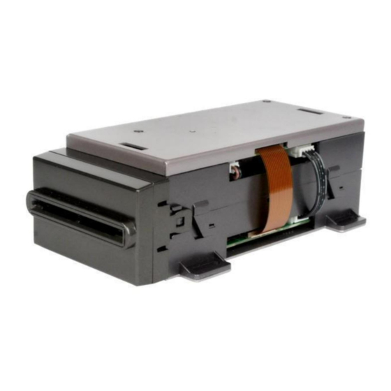
- Page 7 USER MANUAL QU-CM-5510/-2 Ⅴ .COMPONENTS AND PARTS INTRODUCTION ② ① ③ ⑦ ④ ⑤ ⑥ ① ⑤ Top Part of the Main Body Front transmitting wheel ② Top Cover ⑥ Another Part of the Main Body ③ Back transmitting wheel ⑦...
- Page 8 USER MANUAL QU-CM-5510/-2 Ⅵ .OPERATION GUIDE CARD INSERTION NOTE: Magnetic card: The magnetic area under the right side of the card, as picture indicated Contact IC card: Hold the card, the chip IC at the front of the card to insert, as picture indicated.
- Page 9 USER MANUAL QU-CM-5510/-2 Ⅶ .INSTALLATION AND STRUCTURE DRAWING Page 7 of 9...
- Page 10 USER MANUAL QU-CM-5510/-2 Ⅷ .CAUTION DURING OPERATION 1 ) When connecting interface, please connect with communication interface first, then power interface. And then power on. ) To make your product safe, the input voltage please not above 40V. ) Please set BPS rate correct. EX-work set is 9600bps.
- Page 11 QU-CM-5510/-2 Ⅸ.Mantainace 1 . Transmitter maintenance Select “Check transmitter status” in “card reader control command screen”. In normal condition, information of 5 transmitters in text box will all show “No card”. If one or several transmitters show “Have card”, maybe they are covered with dirt.
Need help?
Do you have a question about the QU-CM-5510/-2 and is the answer not in the manual?
Questions and answers