Table of Contents
Advertisement
Quick Links
Advertisement
Table of Contents

Related Manuals for Intellitec BBINT Series

Summary of Contents for Intellitec BBINT Series
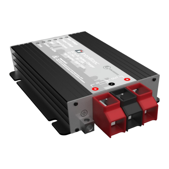
- Page 1 BBINT Series User’s Manual BBINT50A DC/DC Charger V0.5 03/11/2022...
-
Page 2: Table Of Contents
Contents 1. Safety Instruction 1-1 General Safety 1-2 Installation 2. General Information 2-1 Warranty 2-2 Disclaimer 3. Product Description 3-1 Dimensions 3-2 Optional Accessories 3-3 Features 3-4 Specification 4. Installation Instructions 5. Placement and Mounting 6. Connection 7. Configuration 7-1 Default settings 7-2 Dip Switches 7-3 RS-232 Programming 8. -
Page 3: Safety Instruction
1. Safety Instruction WARNING Please read the user manual carefully before use and follow the instructions in the manual. 1-1 General Safety Do not expose the product to rain, snow, water mist or dusty environments to prevent danger and malfunctions. Do not cover or block the ventilation holes of the product. Keep a distance of at least 10 cm around the Charger to allow air to circulate... -
Page 4: Installation
Please note warranty will only be accepted if the product has been used in the correct manner as intended. Misuse including water, foreign objects, dust pollution, corrosion, tampering or deliberate damage, will void warranty, and Intellitec MV Ltd will not be responsible for any repairs. Product failures caused by misuse will be a chargeable repair. -
Page 5: Product Description
3. Product Description The BBINT50A charger converters a DC (battery) voltage to a regulated DC voltage. It can be used as a: • 2-Stage battery charger or • 3-Stage battery charger or • DC power supply. The BBINT50A can only be used in installations with a negative ground. 3-1 Dimensions Unit: mm 136.5... - Page 6 Front Panel Front Panel INPUT OUTPUT COMMON NEGATIVE Rear Panel Rear Panel LIN (For Future Use) Remote Port (Programming Port) Battery Temperature Sensor DIP Switches...
-
Page 7: Optional Accessories
8. OTA Relay Common - Programming Cable (Part NO. K447). The programming cable is to be used in conjunction with Intellitec’s battery to battery charger GUI, which is available to download at the hyperlink below: https://www.intellitecmv.com/pages/downloads Charging Curve with Battery Temperature Compensation 15.0... -
Page 8: Features
3-3 Features • The converter can be fully programmed by DIP Switches or by RS-232 using Intellitec MV GUI software BBINT50, downloadable from Intellitec MV Website • Built-in battery rescue (pre-charging) function • Compatible with Lead Acid, LiFePO4, Gel and AGM batteries •... - Page 9 MODEL BBINT50A Working Temperature 12V : -20 ~ +60 ℃ (De-ra ng by case temperature) Storage Temperature -40 ~ +85 ℃ Environment 95% , non condensing Rela ve Humidity Vibra on IEC68-2-6 Safety Standards EN62368 EMC Standards Meets CE Safety & EMC E-mark E11 / 10R06/00*11580*00 Output Ba ery...
- Page 10 Charger Curve VS Case Temperature De-rating Curve: Charging Curve 100% (Over Temperature Alarm) Case Temperature (°C) Rescue (pre - charging) Curve: Output Current 6.25% Output Current (Func 15 Value) Batery Voltage...
-
Page 11: Installation Instructions
4. Installation Instructions Installation Steps: 1. Place and mount the BBINT50A, see chapter 5 2. Connect the BBINT50A, see chapter 6 3. Configure the BBINT50A, see chapter 7 CAUTION Read the entire manual before installing the BBINT50A. Keep the manual in a safe location for future reference. -
Page 12: Placement And Mounting
5. Placement and Mounting Mount the BBINT50A with four M6 screws (7/32") to a solid flat surface. -
Page 13: Connection
6. Connection • BBINT50A as a battery charger, see installation drawing A. • BBINT50A as a stabilised DC power supply, see installation drawing B. • Use properly sized fuses and wiring. Installation Drawing A REMOTE RS-232 TEMP. Battery Charger Battery Voltage Battery Temp Sensor Sensor... -
Page 14: Configuration
Please note that the dip switches provide basic parameter settings, while the GUI software offers more advanced options. A programming cable (Part No.K447) will be required in order to use the GUI software, which can either be purchased from Intellitec or made using the instructions on page 14 section 7-3. -
Page 15: Dip Switches
• By DIP switches (Basic parameters); • Via RS-232/Intellitec MV GUI software (Basic parameters+advanced features/custom settings). This chapter only describes the DIP switch settings Ensure DIP SW 8 is in position‘1' when using DIP switch settings. Use a small screwdriver to carefully set the required settings. -
Page 16: Rs-232 Programming
Se ng To Use Rs232 Programmed Se ngs To Use DIP S1-S7 Se ngs 7-3 RS-232 Programming: Please follow below drawing to make a communication cable. Alternatively this cable can be purchased through Intellitec MV RJ11 RS232 To BBINT To Computer... -
Page 17: Operation
Temp: Temp. CN1: Igni on/Enable (Ac ve HIGH) BMS+ Enable (Ac ve HIGH) BMS- Enable (Ac ve LOW) Voltage Sensor + (0-17V) Charging Relay Common * Charging Relay Normally Open * OTA Relay Common OTA Relay Normally Open * Charger mode 2 : If the battery temperature is lower than 10 C, and the optional temperature sensor is installed, the relay (CN1-PIN5 &... -
Page 18: Led Indicator
8-2 LED Indicator Use the following table to understand the meaning of the diagnostic LED’s Display LED: Input Voltage LED1 Status Green LED Solid Normal Orange LED Slow Flash Under Voltage Alarm Over Voltage Alarm Orange LED Fast Flash Under Voltage Protec on Shutdown Red LED Slow Flash Red LED Fast Flash Over Voltage Protec on Shutdown... - Page 19 LED4 Status FUNC14 Se ng 1 Green LED Solid BMS+ > FUNC17 or BMS- Input to GND FUNC14 Se ng 1 Red LED Solid BMS+ < FUNC17-0.3V & BMS- Input floaa ng No light FUNC14 Se ng 0 (Default) Status Igni on LED5 Green LED Solid...
-
Page 20: Charging Curve
8-3 Charging Curve BULK(CC) ABSORPTION(CV) BULK(CC) FLOAT RECHARGE FLOAT 14.4 13.8 12.8 Current Voltage Return amps =6.25% of rated current BULK BULK ABSORPTION ABSORPTION FLOAT FLOAT FLOAT FLOAT BULK BULK RECHARGE RECHARGE 2min~8hours 2min~8hours 0.25hours~24hours 0.25hours~24hours 2weeks 2weeks 85mins 85mins 2weeks 2weeks 2min~8hours... -
Page 21: Trouble Shooting
9. Trouble Shooting Malfunction Possible cause Check / Confirm No input voltage Check se ngs No output voltage/ current Input voltage is too low Check input voltage / configura on Ba eries load is larger than Reduce the ba eries load. ba ery charger can supply.
Need help?
Do you have a question about the BBINT Series and is the answer not in the manual?
Questions and answers