
Related Manuals for Mayer TM 2018


Summary of Contents for Mayer TM 2018
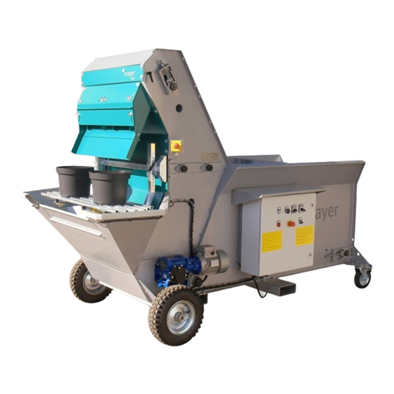
- Page 1 Potting machine TM 2018 Operating instructions Issue date: 01.10.2009 / V1.0 Before the initial start-up, read and keep at the machine for future use.
-
Page 2: Table Of Contents
List of Contents 1 Product description 5 Initial start-up 1. Intended use 1. Check prior to first start 2. Structure 2. Starting the machine for the first time 3. Functional description 3. Stopping the machine 4. Technical Data 5. EU Declaration of conformity 6 Operation 2 General safety instructions 1. -
Page 3: Product Description
1 Product description 1. Intended use The MAYER TM 2018 potting machine may be used for planting round or square containers or and replanting plants into poly bags with a minimum of working force and of time. Other means of use of the machine, besides the ones listed here, are not permitted –... -
Page 4: Structure
2. Structure Standard equipment (basic machine) Version with vibrating grid (optional) Soil chute for 1 workplace Soil chute for 2 workplaces Different pot sizes can be filled... -
Page 5: Functional Description
3. Functional description The empty containers are put onto the pot supports by one person (in case of version with optional vibrator they are put onto the grid). Plates are fixed on endless chains located in elevator housing which take the soil from the soil hopper. When the plates reach the upper turning point the soil falls into container being there by means of the soil chute. -
Page 6: Technical Data
4. Technical data Make: Mayer Machine type: Potting machine Series: 2018 Length / width / height: 300 x 130 x 200 cm Weight: 480 kg Working height: approx. 85 cm Current consumption: 16 A Control voltage: 24 V DC Power connection:... - Page 7 Available accessories (for an additional charge) Soil hopper extension 2,5 m³ • Soil hopper extension 3,5 m³ • Soil hopper extension 4 m³ • Heavy duty wheels in connection with soil hopper extension • Conveyor belts • Roller conveyors and roller curves •...
-
Page 8: Eu Declaration Of Conformity
3. EU declaration of conformity According to Appendix IIA of the EU Machinery Directive (2006/42/EC) Mayer GmbH & Co. KG The manufacturer: Maschinenbau u. Verwaltung Poststrasse 30 89522 Heidenheim | Germany Make: Mayer hereby attests that the machine described in... -
Page 9: General Safety Instructions
2 General safety instructions 1. Due diligence of the operating company The MAYER TM 2018 potting machine was designed and built taking a danger analysis into consideration and after careful selection of the harmonised standards to be complied with as well as other specifications. -
Page 10: Explanation Of The Safety Symbols Used
Before beginning with any work on the machine, The machine may not be started if any safety • • secure its drives and accessory parts against devices are removed. being switched on unintentionally. In the working area the operator is responsible •... -
Page 11: Basic Safety Precautions
3. Basic safety precautions Always be sure that: … tight-fitting working clothes are worn at all the • workplaces. … it is not allowed to wear chains, rings, bracelets or • wristbands. … for operationally relevant reasons, it is not possible to •... -
Page 12: Machine-Related Safety Precautions
4. Machine-related safety precautions The workplaces are spread over various areas of The machine must be set up on even and solid the potting machine. surface so that it stands securely in place. There is danger of life in case of a machine falling a) Filling the soil hopper with substrate from the over. -
Page 13: Demands On Operating Personnel
5. Demands on operating personnel The machine may only be operated by personnel Only trained personnel may ever operate any of the who have been trained for such, shown what is control and safety equipment. involved and are authorised to do so. These individuals have to know and act in accordance with All individuals that carry out any activities with the... -
Page 14: Transport
3 Transport To prevent damage to the machine as well as When transporting the machine, the following injuries while transporting the machine, it is special dangers must be expected: absolutely necessary to comply with the following points: Suspended loads can drop, which would be a •... -
Page 15: Handling
2. Handling The potting machine is fitted with 2 pneumatic tyres on one axle on the front and 2 castors on the soil hopper. The weight of the empty machine is balanced on the axle. The machine can be pushed and pulled. On request, a trailer coupling can also be attached for an extra charge. -
Page 16: Installation
4 Installation 1. General notes To protect the machine against weather caused damages it is suggested to use and store it inside. Electrical connection: 400V/50Hz. Connection is permitted only to socket-outlets which are protected by an AC/DC sensitive RCCB (residual-current circuit- breaker) 0,03A. -
Page 17: Installing The Machine
2. Installing the machine A hard soil surface shall be provided under the machine to prevent the wheels and castors from sinking into the soil. The castors are equipped with a handbrake. 3. Measures for the machine’s stability against overturning There is no need to carry out other activity for erecting the machine than it is described in section 4.2. -
Page 18: Initial Start-Up
5 Initial start-up It is absolutely necessary to comply with the following safety instructions for the initial start-up of the machine. This will prevent injury to individuals, damage to machinery and other property damage. The initial start-up may only be carried out by •... -
Page 19: Starting The Machine For The First Time
1. Starting the machine for the first time After reassembly the machine shall be checked as per the following: Be sure not foreign materials, such as tools or similar, are left in the soil hopper, in the elevator or under the pot supports. Put main switch of the machine to OFF („Null”) position before plug of the connection cable would be connected to the socket. - Page 20 Button Button Controller vibrator START STOP (optional) Switch Emergency Switch vibrator soil stop (optional) Emergency stop...
-
Page 21: Stopping The Machine
3. Stopping the machine There are two ways provided to switch off the machine. In normal case the machine is being controlled by means of the pedal switches. The machine will stop automatically as soon as the pedal switch is being released. In emergency case by „Emergency Stop”... -
Page 22: Operation
6 Operation 1. Normal operation a) Before starting operation the following shall be checked: Are pots, plants and soil mixture available in sufficient • quantity? Care about the following Soil transport • Container preparation • Use the shortest transport routes •... - Page 23 c) Soil feeding of the machine The soil hopper contains 1,500 litres and can be fed in various ways without the work flow at the machine being disturbed or interrupted. Feeding can take place: manually by means of a shovel •...
- Page 24 e) Adjusting soil amount Supply of soil from the soil hopper to the elevator takes place by means of a continuous rubber conveyor belt, running on carrier rollers in the soil hopper. There a 3 options to control the soil amount to be fed: By setting different switch positions on the elevator and rubber conveyor belt: to the right on position “1”...
- Page 25 Setting compactness of the soil in the containers (optionally with special equipment vibrating grid) Special feature of the MAYER potting machine TM 2018 with vibrating unit (optionally) is the possibility to set compactness of the soil in the containers. This depends on the strength of the vibrator.
-
Page 26: Shutting Down The Machine
2. Shutting down the machine There are two ways provided to switch off the machine. In normal case the machine is being controlled by means of the pedal switches. The machine will keep on running as long as the pedal switch is being pressed. In emergency case the machine can by stopped by the „emergency stop”... -
Page 27: Malfunctions
7 Malfunctions To prevent damage to the machine as well as injuries while remedying malfunctions at the machine, it is absolutely necessary to comply with the following points: Only eliminate a malfunction if you have the qualification • specified to do so. Also read the section "General Safety Instructions". -
Page 28: Possible Malfunctions And Trouble Shooting
2. Possible malfunctions and trouble shooting a) Mechanical malfunctions Failure/Malfunction Cause Trouble shooting Noise in the elevator Jammed stone or wooden piece Remove cause for malfunction. Possibly by running elevator backwards (turn switch left to position "1" or "2") Erratic filling of containers Matter in elevator Remove source of interference. -
Page 29: Maintenance
Release pressure of every unit that is under • pressure. Only Mayer GmbH & Co. KG may ever • manipulate the machine's control programme. All un-recycled operational materials, lubricants • and supplies must be disposed of in an environmentally friendly manner. -
Page 30: General Notes
Spare parts have to meet the technical requirements of the machine's manufacturer. This is guaranteed with original spare parts from MAYER. 2. Inspection and preventative maintenance 2.1 Elevator chains Chains may be retensioned by means of tensioning bearings located on two sides of the elevator. -
Page 31: Rubber Conveyor Belt
2.2 Rubber conveyor belt Generally the rubber belt requires no retensioning. However if the belt should be readjusted caused for example by remedy works carried out on the machine, follow the process described below: Tensioning of the belt may be adjusted by means of tensioning nuts located at end of soil hopper. -
Page 32: Maintenance Schedule
3. Maintenance schedule Description Interval Grease elevator chain (prior to a longer shutdown) Grease all bearings fitted with grease nipples yearly... -
Page 33: Part List
9 Part list... - Page 34 ELEVATOR 2018-A000-00-00 ELEVATOR Pos. Benennung Artikelnummer Stück Description Part number Amount Elevator-Gehäuse 2018-A001-00-00 Elevator housing Elevator-Erdförderung ohne 2018-A031-00-00 Getriebe Elevator soil conveyor without drive Motor 108 132/501 876 Motor 6-Kt-Schraube 101 669/500 183 Hexagonal screw Federring 101 606 / 500 077 Spring ring Topfauflage 2018-A021-00-00...
- Page 35 Pos. Benennung Artikelnummer Stück Description Part number Amount U-Scheibe 101 597/500 090 Washer Getriebe 108 160/500 546 Drive unit...
- Page 37 Elevator-Gehäuse 2018-A001-00-00 Elevator housing Pos. Benennung Artikelnummer Stück Description Part number Amount Gehäuse 2018-A001-01-00 Housing Erdblende 2018-A001-04-01 Soil port Blech 2018-A001-02-00 Plate 6-Kt-Schraube 101 768 / 500 169 Hexagonal screw U-Scheibe 101 596/500 089 Washer Erdblende oben 2018-A001-17-01 Upper soil port 6-Kt-Mutter 101 688 / 500 222 Hexagonal nut...
- Page 39 Weiche 2018-A011-00-00 Deflector Pos. Benennung Artikelnummer Stück Description Part number Amount Erdrutsche 2018-A011-01-00 Soil chute Abnäher 2018-A011-07-01 Constrictor Weiche rechts 2018-A011-02-00 Deflector right Weiche mitte I. 2018-A011-04-00 Deflector middle I. Weiche mitte II. 2018-A011-05-00 Deflector middle II. Weiche links 2018-A011-03-00 Deflector left Abschlussblech 2018-A011-06-01...
- Page 41 Topfauflage 2018-A021-00-00 Pot support Pos. Benennung Artikelnummer Stück Description Part number Amount U-Halter 2018-A001-15-01 U-Holder Träger 2018-A001-06-00 Beam Schutz 2018-A001-09-00 Protecting Flachstahl 2018-A001-22-01 Flat-iron Halter 2018-A001-05-01 Holder Klemmhebel 112 921/500 306 Clamping lever Haltewinkel 2018-A001-07-00 Holder plate Halter 2018-A001-19-00 Holder Buschse BB345SINT Bushing...
- Page 43 Elevator-Erdförderung ohne Getriebe 2018-A031-00-00 Elevator soil conveyor without drive Pos. Benennung Artikelnummer Stück Description Part number Amount Antriebswelle 1010-01-03-01-00 Drive shaft Umlenkwelle 1010-01-03-15-00 Deflecting shaft Umlenkwelle 1010-01-03-12-00 Deflecting shaft Förderkette links 1012-01-03-20-00 Hollow bolt chain left Antriebsrad 1010-01-03-06-00 Driving pulley Flanschlager 102 182 Flange bearing...
- Page 44 Pos. Benennung Artikelnummer Stück Description Part number Amount Haltewinkel links 1010-01-03-20-03 Bracket left 6-Kt-Mutter 101 688 / 500 222 Hexagonal nut Federring 101 605 / 500 076 Spring ring Flachrundschraube 101 687 / 500 066 Half-round head screw Schaufel 1010-01-03-36-01 Shovel blade Schaufel 1010-01-03-35-01...
- Page 46 Erdbehälter 2018-B000-00-00 Soil hopper Pos. Benennung Artikelnummer Stück Description Part number Amount Blech 1010-B001-05-01 Plate Handgriff 1010-B001-07-01 Handhold Konsole für Lenkrolle 1010-0299-832 Console by wheel Schutzblech 1010-B001-08-01 Guard 6-Kt-Schraube 109 878 / 500 112 Hexagonal screw U-Scheiben 101 596 / 500 089 Washer 6-Kt-Schraube 105 040 / 500 184...
- Page 47 Pos. Benennung Artikelnummer Stück Description Part number Amount 6-Kt-Mutter 101 614 / 500 226 Hexagonal nut Bundmutter 1010-01-03-09-03 Flange nut Spindel 1010-02-02-04-01 Spindle U-Scheibe 101 620 / 500 351 Washer 6-Kt-Mutter 107 536 / 500 226 Hexagonal nut Schutzblech 2400-B001-11-01 Guard Spindel 1010-02-02-08-00...
- Page 48 Pos. Benennung Artikelnummer Stück Description Part number Amount Zugstange 2105-01-03-08-00 Connecting rod Zylinder-Schraube 101 737 / 500 276 Cylinder head screw Distanzscheibe 1010-01-03-03-03 Distance bracket disk Zylinderrollenlager 102 201 / 500 325 Cyindrical roller bearing Exzenter 1010-01-03-07-00 Eccentric Collar Gewindestift 101 748 / 500 030 Threaded pin Freilauf...
- Page 49 Pos. Benennung Artikelnummer Stück Description Part number Amount Rolle 1010-02-02-05-01 Roller Achse 1010-02-02-05-02 Axle Sicherungsring für Welle 101 623 / 500 897 Retaining ring Rillenkugellager 102 194 / 500 338 Ball bearing Antriebsrolle 1010-02-02-01-00 Driving roller Seitenwand rechts 1010-B001-02-00 Side wall right Eckblech 1010-B021-01-01 Corner plate...
- Page 50 Elevator soil conveyor without drive...
- Page 51 Vibrator 2018-V002-00-00 Vibrator Pos. Benennung Artikelnummer Stück Description Part number Amount Halter 2018-V002-04-00 Holder Gummi 2018-V002-03-01 Rubber Klemmhebel 112 921/500 306 Clamping lever Gitter 2018-V002-01-00 Grate Haltewinkel 2018-V002-02-00 Bracket Gummi feder 505 113 Rubber spring Federring 101 605 / 500 076 Spring ring Selbsts.
-
Page 53: Circuit Diagrams For Electric And Pneumatic System
10 Circuit diagrams for electric and pneumatic system... -
Page 54: Guarantee
11 Guarantee Horticultural machinery and special machinery We will accept liability for faults in the supplied goods and for any failure to provide features for the existence of which an express assurance had been given. In such a case we undertake –... - Page 55 You have chosen to purchase a product of true quality. We wish you every success with your product. We would be most grateful if you would recommend our products to others. Thank you Your MAYER-TEAM...
Need help?
Do you have a question about the TM 2018 and is the answer not in the manual?
Questions and answers