Advertisement
Do not drill holes in the floor until after you have installed
the cables and hoses and used the floor cover to ensure
your posts are at the correct distance apart.
Do not attempt to preset your anchors in wet concrete. This
is completely unnecessary and has a high possibility of
error that cannot be corrected.
Call 866-563-5438 For Help
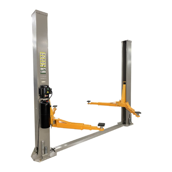
Two-Post Floor Plate Lift
(11,000 lbs. Capacity)
TRIUPMH AUTO LIFTS
TRIUPMH AUTO LIFTS
TRIUPMH AUTO LIFTS
INSTRUCTION MANUAL
NT-11
1
Advertisement
Table of Contents

Related Manuals for Triumph NT-11


Summary of Contents for Triumph NT-11
- Page 1 Call 866-563-5438 For Help NT-11 Two-Post Floor Plate Lift (11,000 lbs. Capacity) TRIUPMH AUTO LIFTS TRIUPMH AUTO LIFTS TRIUPMH AUTO LIFTS INSTRUCTION MANUAL Do not drill holes in the floor until after you have installed the cables and hoses and used the floor cover to ensure your posts are at the correct distance apart.
-
Page 2: Important Notes
Floor Plate Height Width height 11000lbs 112” NT-11 Asymmetric 56 Sec 116' 138” 72” The installation of this lift is relatively simple and can be accomplished by 2 strong persons in a few hours. The following tools and equipment are needed: •... -
Page 3: General Information
Call 866-563-5438 For Help GENERAL INFORMATION 1. Carefully remove the crating and packing materials. CAUTION! Be careful when cutting steel banding material as items may become loose and fall causing personal harm or injury. 2. Identify the components and check for damage or shortages. Please contact your distributor immediately, if any damages or shortages are discovered. - Page 4 Call 866-563-5438 For Help TRIUPMH AUTO LIFTS TRIUPMH AUTO LIFTS TRIUPMH AUTO LIFTS 4...
-
Page 5: Installation Instructions
Call 866-563-5438 For Help INSTALLATION INSTRUCTIONS STEP 1: (Selecting Site) Before installing your new lift, check the following: LIFT LOCATION: Always use architects plans when available. Check layout dimension against floor plan requirements making sure that adequate space is available (Fig. 2 & Fig. 3). Place 102 inch long plate on floor and push posts against plate to get correct width. - Page 6 Call 866-563-5438 For Help OVERHEAD OBSTRUCTIONS: The area where the lift located should be free of overhead obstructions such as heaters, building supports, electrical lines etc (Fig. 4) TRIUPMH AUTO LIFTS TRIUPMH AUTO LIFTS TRIUPMH AUTO LIFTS <______________________________________138"___________________________________> DEFECTIVE CONCRETE: Visually inspect the site where the lifts will be installed and check for cracked or defective concrete.
- Page 7 Call 866-563-5438 For Help STEP 2: (Unloading and Unpacking) After unloading the lift, place it near the intended installation location. Remove the shipping bands and packing materials from the unit. Remove the packing brackets and bolts holding the two columns together. Take out the up-rights, lifting arms, pads, accessory box, hoses, etc, from the column.
- Page 8 Call 866-563-5438 For Help Using the base plate on the MAINSIDE column as a guide, drill each anchor hole in the concrete to at minimum 5 ” deep using a rotary hammer drill and ” concrete drill-bit. To assure full holding power, do not ream the hole or allow the drill to wobble.
- Page 9 Call 866-563-5438 For Help STEP 6: (Mounting the POWER UNIT) Attach the power unit to the POWERSIDE COLUMN using bolts, nuts and washers supplied (Fig. 10). Remove the vent plug from the power unit and fill the reservoir with hydraulic oil. Make sure the funnel used to fill the power unit is clean. Suggestion: Use AW 32, or 46 Non-Detergent Non-Foaming Anti-Wear Hydraulic Oil SAE-10 or Automotaic Transmission Fluid.
- Page 10 Call 866-563-5438 For Help Cable Route Diagram TRIUPMH AUTO LIFTS TRIUPMH AUTO LIFTS Fig. 13 Repeat above for the second cable. TRIUPMH AUTO LIFTS Adjust each equalizer cable to approximately 1/2” side-to-side play. Ensure that each cable has equal tension. Also, check the carriage height to ensure both carriages are sitting on the same latch. STEP 8: (Connecting the Hydraulic Hoses) As shown on Figs.
- Page 11 Call 866-563-5438 For Help Hose Route Diagram TRIUPMH AUTO LIFTS TRIUPMH AUTO LIFTS Fig. 18 TRIUPMH AUTO LIFTS Fig. 16 STEP 9: (Installing Lifting Arms & Arm Restraints) Install the lifting swing arms on the carriages using included 1-1/2” diameter pins.
- Page 12 Call 866-563-5438 For Help Fig. 19 STEP 11: (Electrical connection) Make the Electrical hookup to the power unit (220V Single Phase). Important: the wiring must comply with local code. Have a certified electrician make the electrical hook-up to the TRIUPMH AUTO LIFTS power unit.
- Page 13 Call 866-563-5438 For Help PERFORMANCE RAISE LIFT 1. Read operating and safety manuals before using lift. 2. Always lift a vehicle according to the manufacturers recommended lifting points 3. Position vehicle between columns. 4. Adjust swing arms so that the vehicle is positioned with the center of gravity midway between pads. 5.
-
Page 14: Safety Procedures
Call 866-563-5438 For Help SAFETY PROCEDURES Never allow unauthorized persons to operate lift. Thoroughly train new employees in the operation and care of lift. Caution: the power unit operates at high pressure. Remove passengers before raising vehicle. Prohibit unauthorized persons from being in shop area while lift is in use. Total lift capacity is 11,000Lbs with 2,750lbs per arm pad. -
Page 15: Maintenance Schedule
Call 866-563-5438 For Help MAINTENANCE SCHEDULE The following periodic maintenance is the suggested minimum requirements and minimum intervals; accumulated hours or monthly period, which ever comes sooner. If you hear a noise or see any indication of impending failure - cease operation immediately –... - Page 16 Call 866-563-5438 For Help YEARLY MAINTENANCE Grease rub blocks and column surface contacting rub blocks with dry or Teflon based lube (Spray Lube) Change the hydraulic fluid. Good maintenance procedure makes it mandatory to keep hydraulic fluid clean. No hard fast rules can be established;-operating temperature, type of service, contamination levels, filtration, and chemical composition of fluid should be considered.
-
Page 17: Troubleshooting
Call 866-563-5438 For Help TROUBLE SHOOTING Motor does not run: Breaker or fuse blown Faulty wiring connections. Call electrician. Defective up button. Call electrician for checking. Defective Capacitor. Call electrician for checking. Motor runs but will not raise: A. Oil level to low. Oil level should be just under the vent cap port when the lift is down!!! B. -
Page 18: Owner / Employer Responsibilities
Call 866-563-5438 For Help Lift makes excessive noise. Carriage of the lift is dry and requires grease. Grease corners of columns. Cylinder pulley assembly or cable pulley assembly is not moving freely. Check and grease it. May have excessive wear on pins or cylinder yoke. Check and replace them. Seals are dry in hydraulic Cylinder(s).
Need help?
Do you have a question about the NT-11 and is the answer not in the manual?
Questions and answers