
Related Manuals for Triumph NTO-9AE


Summary of Contents for Triumph NTO-9AE
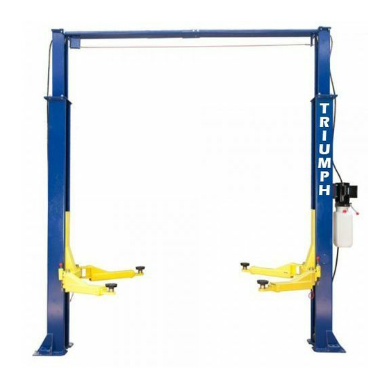
- Page 1 N TO-9AE Overhead Beam Style Lift 9,000 POUND Two Post Lift ASSEMBLY & OPERATION INSTRUCTION...
- Page 2 TABLE OF CONTENTS Important Note Page 3 Definition Page 4 Preparation and General Information Page 5 Important Concrete and Anchoring Information Page 6 Installation and Basic Operation instruction Page 8 Safety procedures Page 10 Maintenance Schedule Page 11 Troubleshooting Page 13 Owners Responsibilities Page 14 (Fig 1 and Fig 2)
- Page 3 IMPORTANT NOTES ● Do not install this lift on an asphalt surface. ● Do not install this lift on any surface other than concrete confirming to minimum specifications. ● Do not install this lift over expansion joints or cracks. Check with an engineer. ●...
- Page 4 DEFINITION This lift is a 9000 lb. capacity, 2-Post Lift with a latch system. The safety latch is in contact with the latch rack as the lift ascends and drops into place. The safety latch engages in rack at 3” increments beginning about 16”from the ground.
- Page 5 PREPARATION The installation of this lift is relatively simple and can be accomplished by 2 people in a few hours. The following tools and equipment are needed: • 12 quarts of Non-Detergent Hydraulic Oil SAE-10 AW 32 or other good grade •...
- Page 6 IMPORTANT CONCRETE AND ANCHORING INFORMATION 1. Concrete shall have compression strength of at least 3,000psi and a minimum thickness of 4” in order to achieve a minimum anchor depth of 3 1/2”. If the top of the anchor exceeds 2” above the floor grade, you DO NOT have enough depth. 2.
- Page 7 ANCHORING TIP SHEET Anchors must be at least 6”from the edge of the slab or any seam. 1. Use a concrete hammer and a drill, a solid drill bit with a carbide tip, the same diameter as the anchor, 5/8”. Do not use excessively worn bits or bits that have been incorrectly sharpened.
- Page 8 INSTALLATION INSTRUCTION FOR FLOOR PLATE STYLE AND OVERHEAD BEAM STYLE 2-COLUMN HYDRAULIC LIFTS PLEASE READ THIS INSTRUCTION BEFORE STARTING TO INSTALL THE LIFT STEP 1: After unloading the lift, place it near the installation location. STEP 2: Remove the shipping bands and packing materials from the unit. STEP 3: Remove the packing brackets and bolts holding the two columns together.
- Page 9 dimensions, install overhead beam to top of columns BEFORE drilling anchors for offside column to insure column level. STEP 10: After overhead beam is assembled drill and anchor offside column as described in steps 7 and 8. STEP 11: Figure 6 Page 20 Install the equalizing cables: Refer to figure for general cable arrangement for both Floor Plate Style and Overhead Beam Style Lifts.
- Page 10 STEP 16: Figure 4 Page 18 For Floor Plate Style Lift, mount the floor plate as Figure 4. STEP 17: Install the swing arms on the carriages using the included 1 1/2” diameter pins. Check to make sure the rack on the lock should fully engage with the gear on the arm. STEP 18: Adjust the carriage cables tension: adjust each cable to approximately 1/2”...
- Page 11 LOWER THE LIFT 1. Raise the lift until the latch clears. 2. Pull both latch releases. WARNING ALWAYS RELEASE BOTH SIDES 3. Press the lever at the power unit to lower the lift. SAFETY PROCEDURES Never allow an unauthorized person to operate lift. Thoroughly train new employees in the use and care of the lift.
- Page 12 IT IS IMPORTANT TO INSPECT LIFTING EQUIPMENT AT THE START OF EVERY SHIFT. THESE AND OTHER PERIODIC INSPECTIONS ARE THE RESPONSIBILITY OF THE USER. DAILY PRE-OPERATION CHECK (8 HOURS) The user should perform daily check. ATTENTION! Daily check of safety latch system is very important and the discovery of device failure before needed could save you from expensive property damage, lost production time, serious personal injury or even death.
- Page 13 environment shorter interval may be required. The following items should only be performed by a trained maintenance expert. Replace hydraulic hoses. Replace chains and rollers. Replace cables and sheaves. Replace or rebuild air and hydraulic cylinders as required. Replace or rebuild pumps/motors as required. Check hydraulic and air cylinder rod and rod end (threads) for deformation or damage.
- Page 14 4. Motor hums and will not run: A. Impeller fan cover is dented. Take off and straighten. B. Faulty wiring. Call electrician C. Bad capacitor. Call electrician D. Low voltage. Call electrician E. Lift overloaded. Reduce load. 5. Lift jerks going up and down: air in hydraulic system. Raise lift all the way to the top and return to floor.
- Page 15 ** WARNING** All Dimensions Are Approximate. Always Start By Anchoring the Power Unit Side leg. Then Use Floor Plate or Overhead Beam Too Locate The Second Leg Properly. Never Drill Anchor Holes Without Legs In Place.
- Page 16 INSTALLATION INSTRUCTION Fig 1 For Floor Plate Lift Floor Plate/Overhead Style Lifts...
- Page 17 INSTALLATION INSTRUCTION Fig 2 For Overhead Lift Floor Plate/Overhead Style Lifts...
- Page 18 INSTALLATION INSTRUCTION Fig 3 Asymmetric Type Floor Plate/Overhead Style Lifts...
- Page 19 INSTALLATION INSTRUCTION Fig 4 Prepare Concrete Floor Plate/Overhead Style Lifts...
- Page 20 INSTALLATION INSTRUCTION Fig 5 Upright, Overhead Beam Assembly Floor Plate/Overhead Style Lifts...
- Page 21 INSTALLATION INSTRUCTION Fig 6 Equalizing Cable Installation – Overhead Beam Type Floor Plate/Overhead Style Lifts...
- Page 22 INSTALLATION INSTRUCTION Fig 7 Equalizing Cable Installation – Floor Plate Type Floor Plate/Overhead Style Lifts...
- Page 23 INSTALLATION INSTRUCTION Fig 8 Hydraulic System Assembly – Floor Plate Type Floor Plate/Overhead Style Lifts...
- Page 24 INSTALLATION INSTRUCTION Fig 9 Hydraulic System Assembly – Overhead Beam Type Floor Plate/Overhead Style Lifts...
- Page 25 Floor Plate/Overhead Style Lifts...
- Page 26 Floor Plate/Overhead Style Lifts...
- Page 27 Floor Plate/Overhead Style Lifts...
- Page 28 Floor Plate/Overhead Style Lifts...
- Page 29 Floor Plate/Overhead Style Lifts...
- Page 30 Floor Plate/Overhead Style Lifts...
- Page 31 Floor Plate/Overhead Style Lifts...
- Page 32 Floor Plate/Overhead Style Lifts...
- Page 33 Floor Plate/Overhead Style Lifts...
- Page 34 Floor Plate/Overhead Style Lifts...
- Page 35 ** CAUTION** Never Start Lift Motor When The Pump Is Under A Load. Always Start Lift Motor From Ground Position Or From Lift Locks. Failure To Do This Can Burn Up Lift Motor And Void Motor Warranty. Always Lower Lift onto Lift Locks.
Need help?
Do you have a question about the NTO-9AE and is the answer not in the manual?
Questions and answers