Table of Contents
Advertisement
Quick Links
Application Note
RX230 Group, RX231 Group
Initial Settings and Usage Procedure of RTC Battery Backup Function
Summary
This application note describes the initial settings and usage procedure of the battery backup function
incorporated into RX230 Group and RX231 Group MCUs, utilizing Firmware Integration Technology (FIT)
module APIs.
For details of the specifications of the RX230 Group and RX231 Group, refer to RX230 Group, RX231 Group
User's Manual: Hardware.
Target Devices
RX230 Group and RX231 Group 64- and 100-pin package products
When using this application note with other Renesas MCUs, careful evaluation is recommended after making
modifications to comply with the alternate MCU.
Related Application Notes
Application notes related to this application note are listed below. Consult them in conjunction with this
application note.
• Firmware Integration Technology User's Manual (R01AN1833)
• RX Family Adding Firmware Integration Technology Modules to Projects (R01AN1723)
• RX Family Adding Firmware Integration Technology Modules to CS+ Projects (R01AN1826)
• RX Family Board Support Package Module Using Firmware Integration Technology (R01AN1685)
• RX231 Group Renesas Starter Kit Sample Code (e
2
studio for CC-RX) (R01AN3137)
• RX Family Battery Backup Function Module Firmware Integration Technology (R01AN2796)
• RX Family Flash Module Using Firmware Integration Technology (R01AN2184)
• RX231 Group Renesas Starter Kit User's Manual (R20UT3027EG)
• Renesas Starter Kit for RX231 CPU Board Schematics (R20UT3026EG)
R01AN4831EJ0100 Rev.1.00
Page 1 of 23
Aug.20.19
Advertisement
Table of Contents

Related Manuals for Renesas RX230 Series


Summary of Contents for Renesas RX230 Series
- Page 1 User’s Manual: Hardware. Target Devices RX230 Group and RX231 Group 64- and 100-pin package products When using this application note with other Renesas MCUs, careful evaluation is recommended after making modifications to comply with the alternate MCU. Related Application Notes Application notes related to this application note are listed below.
-
Page 2: Table Of Contents
Overview ..........................4 About this Application Note ........................4 Operating Environment ........................... 7 Hardware ..........................9 Overview of Renesas Starter Kit for RX231 (RSK) ................. 9 Pins Used ..............................9 Clock Settings ............................10 LCD Panel ............................. 10 Hardware Modifications ......................... 10 2.5.1... - Page 3 RX230 Group, RX231 Group Initial Settings and Usage Procedure of RTC Battery Backup Function Revision History ..........................23 R01AN4831EJ0100 Rev.1.00 Page 3 of 23 Aug.20.19...
-
Page 4: Overview
RX230 Group, RX231 Group Initial Settings and Usage Procedure of RTC Battery Backup Function 1. Overview 1.1 About this Application Note The battery backup function uses a dedicated battery backup power supply (VBATT) to ensure that the RTC’s clock function continues to operate even if the VCC power supply is interrupted. In the operation example described below, time information from the RTC is displayed on an LCD panel, allowing confirmation that the RTC continues to operate when in the battery backup state. - Page 5 RX230 Group, RX231 Group Initial Settings and Usage Procedure of RTC Battery Backup Function Table 1.1 Operating Conditions VBATT Pin Voltage Voltage Drop Monitor 0 Detection Data Saved VCC/VBATT Reset Interrupt Count (RAM, Time State (Vdet0) (Vdetvbt) Operation Display Information) Initialization Input Capture (initial state)
- Page 6 RX230 Group, RX231 Group Initial Settings and Usage Procedure of RTC Battery Backup Function A system flowchart of the sample program is shown below. VCC on Initialize LCD Check whether battery voltage VBATRLVDETF == 2? has dropped below 1.8V Initialize sub clock oscillator, RTC Battery backup power setting and switch count supply voltage drop...
-
Page 7: Operating Environment
Table 1.2 Operating Environment Item Description MCU used R5F52318ADFP (RX231 Group) Board used Renesas Starter Kit for RX231 (product number: R0K505231S000BE) CPU operating frequency Refer to 2.3, Clock Settings. Integrated development Renesas Electronics environment studio Version 7.5.0 C compiler Renesas Electronics C/C++ Compiler Package for RX Family V.3.01.00... - Page 8 Table 1.3 lists the FIT modules used, Table 1.4 list the sample code provided with RSK board, and Table 1.5 lists the SC components. For details of the LCD display software, refer to RX231 Group: Renesas Starter Kit Sample Code (e studio for CC-RX) (R01AN3137EG0200).
-
Page 9: Hardware
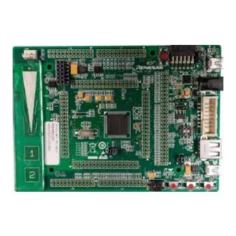
RX230 Group, RX231 Group Initial Settings and Usage Procedure of RTC Battery Backup Function 2. Hardware 2.1 Overview of Renesas Starter Kit for RX231 (RSK) Excerpted from RSKRX231 manual Expansion board Pmod connector Pmod connector interface (application header) Reset switch... -
Page 10: Clock Settings
RX230 Group, RX231 Group Initial Settings and Usage Procedure of RTC Battery Backup Function 2.3 Clock Settings Table 2.2, Clock Settings, lists the clocks used by the sample program. Table 2.2 Clock Settings Operating Clock Frequency Multiplication Name Frequency Source Dividing Ratio Factor ⎯... -
Page 11: Rtcic1 Input
RX230 Group, RX231 Group Initial Settings and Usage Procedure of RTC Battery Backup Function Figure 2.2 Excerpt from RSKRX231 User’s Manual Figure 2.3 VBATT Circuit Detail Excerpted from RSKRX231 CPU Board Schematics 2.5.2 RTCIC1 Input The RX231 RSK board is designed SW1 for IRQ1 (RTCIC1) input and it is set to “pull-up by VCC.” It is therefore necessary to make the following modifications. -
Page 12: Software
RX230 Group, RX231 Group Initial Settings and Usage Procedure of RTC Battery Backup Function 3. Software The configuration and functions of the software referenced in this application note are described below. The folder containing the files generated automatically by the FIT modules and SC is smc_gen, which is in the src folder. -
Page 13: Constants
RX230 Group, RX231 Group Initial Settings and Usage Procedure of RTC Battery Backup Function Table 3.4 Option-Setting Memory Settings Symbol Bit Name Function Setting Value b1, b0 VDSEL[1:0] Voltage detection 0 level 2.51 V is selected. select bits LVDAS Voltage detection 0 circuit Voltage monitoring 0 reset is start bit enabled after a reset. -
Page 14: Function Specifications
RX230 Group, RX231 Group Initial Settings and Usage Procedure of RTC Battery Backup Function 3.8 Function Specifications User setting functions are described below. For information on FIT module functions, refer to the specifications of the relevant module. 3.8.1 main Table 3.8 main Function Item Details Function Name... -
Page 15: Display_Info
RX230 Group, RX231 Group Initial Settings and Usage Procedure of RTC Battery Backup Function 3.8.4 display_info Table 3.11 display_info Function Item Details Function Name display_info () Outline Display battery/switch state function Declaration void display_ info (uint8_t) Description Displays the battery and switch states on the LCD. Functions called R_LCD_Display () Arguments... -
Page 16: Flowcharts
RX230 Group, RX231 Group Initial Settings and Usage Procedure of RTC Battery Backup Function 4. Flowcharts Flowcharts of the functions used by the user file described in this application note are shown below. 4.1 main Function: main() Figure 4.1 is a flowchart of the main processing routine. main Start voltage detection circuit R_Config_LVD1_Start() -
Page 17: Erase Data Flash Function: Flash_Init ()
RX230 Group, RX231 Group Initial Settings and Usage Procedure of RTC Battery Backup Function 4.2 Erase Data Flash Function: flash_Init () Figure 4.2 is a flowchart of the function for erasing the data flash. flash_Init Erase data flash R_FLASH_Erase() Data flash blank check R_FLASH_BlankCheck() RETURN Figure 4.2 Erase Data Flash Function... -
Page 18: Battery Status And Switch Push Count Display Function: Display_Time()
RX230 Group, RX231 Group Initial Settings and Usage Procedure of RTC Battery Backup Function 4.4 Battery Status and Switch Push Count Display Function: display_time() Figure 4.4 is a flowchart of the function for displaying the battery status and switch push count on the LCD. display_info batty_err = 1? Set “ALERT”... -
Page 19: Save Time Information Function: Backup_Time()
RX230 Group, RX231 Group Initial Settings and Usage Procedure of RTC Battery Backup Function 4.5 Save Time Information Function: backup_time() Figure 4.5 is a flowchart of the function for saving time information to the data flash (Vdet1 interrupt processing). backup_time Read RTC information R_Config_RTC_Get_CalendarCounterValue() Set year, month, day, hour, minute,... -
Page 20: Lcd Display And Rtc Input Capture Operation
RX230 Group, RX231 Group Initial Settings and Usage Procedure of RTC Battery Backup Function 5. LCD Display and RTC Input Capture Operation 5.1 LCD Display The sample program displays data information on the LCD screen as described as below. Time information: year/month/day and hour/minute/second VBATT drop alert and switch push count RTC input capture time information: month/day and hour/minute/second Flash save data: year/month/day, hour/minute/second, VBATT drop alert/switch push count... -
Page 21: Battery Backup Operation Disruption
RX230 Group, RX231 Group Initial Settings and Usage Procedure of RTC Battery Backup Function Figure 5.3 Display After VCC Recovery When VBATT drops below 2.2V while VCC is on, an alert is displayed. Figure 5.4 Alert Display When VBATT Drops 5.1.2 Battery Backup Operation Disruption If VCC is turned on after VCC and VBATT were cut off, the time information and SW2 push count saved at the previous time VCC dropped is displayed on the LCD screen. -
Page 22: Rtc Input Capture Operation
RX230 Group, RX231 Group Initial Settings and Usage Procedure of RTC Battery Backup Function 5.2 RTC Input Capture Operation P30~32 pin can be used as peripheral functions such as serial communication, and RTC input capture function. Setting operation function should be done during MCU is powered by VCC. Moreover, during VCC powers, all functions multiplexed can be used. - Page 23 RX230 Group, RX231 Group Initial Settings and Usage Procedure of RTC Battery Backup Function Revision History Description Rev. Date Page Summary ⎯ 1.00 Aug. 20, 2019 First edition issued R01AN4831EJ0100 Rev.1.00 Page 23 of 23 Aug.20.19...
- Page 24 Unit Products The following usage notes are applicable to all Microprocessing unit and Microcontroller unit products from Renesas. For detailed usage notes on the products covered by this document, refer to the relevant sections of the document as well as any technical updates that have been issued for the products.
- Page 25 Renesas Electronics disclaims any and all liability for any damages or losses incurred by you or any third parties arising from the use of any Renesas Electronics product that is inconsistent with any Renesas Electronics data sheet, user’s manual or other Renesas Electronics document.
Need help?
Do you have a question about the RX230 Series and is the answer not in the manual?
Questions and answers