Table of Contents
Advertisement
V2021.08.31
PRODUCT MANUAL
Hot Water Pressure Washer
4000PSI Hot Water Pressure Washer
14HP KOHLER
Powered, 245US Gallon Water Tank
®
MODEL: TMG-HW41T
Please read the product manual completely before assembly
Check against the parts list to make sure all parts are received
Wear proper safety goggles or other protective gears while in assembly
Missing parts or questions on assembly?
Please call: 1-877-761-2819 or email: cs@tmgindustrial.com
Do not return the product to dealer, they are not equipped to handle your requests
WWW.TMGINDUSTRIAL.COM
Toll Free:1-877-761-2819
Advertisement
Table of Contents

Related Manuals for TMG TMG-HW41T


Summary of Contents for TMG TMG-HW41T
- Page 1 14HP KOHLER Powered, 245US Gallon Water Tank ® MODEL: TMG-HW41T Please read the product manual completely before assembly Check against the parts list to make sure all parts are received Wear proper safety goggles or other protective gears while in assembly Missing parts or questions on assembly? Please call: 1-877-761-2819 or email: cs@tmgindustrial.com...
-
Page 2: Table Of Contents
Table of Contents IMPORTANT SAFETY INFORMATION ....................3 SPECIFICATIONS ............................6 INTRODUCTION ............................7 GLOSSARY OF TERMS ..........................8 COMPONENT IDENTIFICATION ......................9 OPERATING INSTRUCTIONS ........................ 12 CHEMICAL APPLICATION ........................15 WINTER PUMP/ COIL PROTECTION ....................16 GENERAL MAINTENANCE ........................16 MAINTENANCE CHECKLIST ........................ -
Page 3: Important Safety Information
IMPORTANT SAFETY INFORMATION The safe operation of our pressure washing systems is the FIRST priority . This will only be achieved by following the operation and maintenance instructions as explained in this manual and all other enclosed manuals. This manual contains essential information regarding the safety hazards, operations, and maintenance associated with this machine. - Page 4 WARNING: Risk of fire. Do not add fuel when operating machine. 3. Never use gasoline, crankcase draining, or waste oil in your burner fuel tank. Never run pump dry or let the pump run with the trigger gun released for more than 2 minutes. The minimum clearance to any combustible material is 12 inches.
- Page 5 WARNING: Trigger gun kicks back. Hold with both hands. 7.Hold firmly to the gun and wand during start up and operation of the machine. Do not attempt to make adjustments while the trigger gun is in operation. 8.Make sure all quick coupler fittings are properly secured before operating pressure washer.
-
Page 6: Specifications
BURNER OIL ELECTRIC MODEL HP/ ENGINE DRIVE BURNER PRESSURE (PSI) START TMG-HW41T 4000 300,000 14 KOHLER Direct WW W . T M G I ND U S T R I A L . C O M P0 6 / 4 1... -
Page 7: Introduction
INTRODUCTION Thank you for selecting a quality product. We are pleased to have you included among the many satisfied owners of cleaning machines. Years of engineering have gone into the development of these fine products and only top quality components and materials are used throughout. Each machine is carefully tested and inspected before leaving our plant to ensure years of dependable performance. -
Page 8: Glossary Of Terms
GLOSSARY OF TERMS PSI – Pounds per square inch. Pressure washers are designed and rated to operate at a specific PSI. Operating at pressures exceeding the maximum rating could result in damage to the unit and/or SEVERE PERSONAL INJURY. GPM – Gallons per minute. The orifice on the pressure wand assembly has been selected to deliver up to the maximum GPM for your machine. -
Page 9: Component Identification
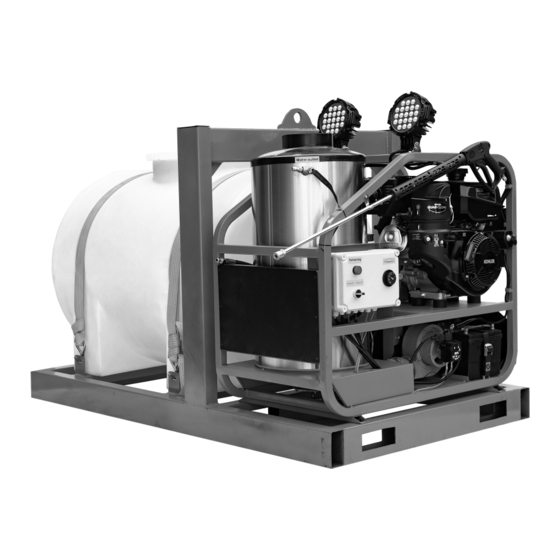
COMPONENT IDENTIFICATION Two 60W LED Lifting Eye Work Light 245 US Gallon Water Tank Fork Lift Slots Direct Driven Pump Assembly: Adjust Pressure Switch Chemical Injector Water Outlet Water Inlet Water Pump WW W . T M G I ND U S T R I A L . C O M P0 9 / 4 1 T ol l Fr e e : 1 - 8 7 7 - 7 6 1 - 2 8 1 9... - Page 10 Electrical Control Center: Important Note: This high pressure washer is a hot and cold machine. If you do not use hot water, do not operate the electrical control center Switch: 1. HOT WATER: Hot water button switch -When using hot water to clean, first need to press this switch. The switch comes with self-locking function, press once to connect, press again to disconnect.
- Page 11 Hot Water Tank Interior (Top Cover Removed): Coil Ceramic Casing Inner Steel Layer Coil Skin (outer Pressure Wand Assembly: stainless steel pray Gun Nozzle Quick Coupler Trigger Black Nozzle for Wand Nozzles Downstream Chemical Application High Pressure Hose WW W . T M G I ND U S T R I A L . C O M P1 1 / 4 1 T ol l Fr e e : 1 - 8 7 7 - 7 6 1 - 2 8 1 9...
-
Page 12: Operating Instructions
OPERATING INSTRUCTIONS 1.Perform pre-start maintenance inspection on all applicable systems prior to operating the machine. This is essential for the safe, effective and efficient operation. You will get optimum performance from your system ONLY if these instructions and inspections are followed. Any indication that the pressure washing system was not operated and maintained according to these instructions may cancel the manufacturers’... - Page 13 2.Attach high-pressure hose to hot water outlet quick connector. Attach the other end of high pressure hose (with quick coupler) to spray gun. Ensure that quick disconnect connections are tightly locked together. Apply a sharp pull on hose to confirm they are secured. Attach wand nozzle specific to task requirements (i.e.
- Page 14 5.Burner operation Be sure water is flowing through water heater coil before turning on HOT WATER switch. Turn thermostat to desired temperature. Burner will ignite and remain in operation as long as there is sufficient water flow to satisfy the pressure switch and temperature control. IF YOU EXPERIENCE IGNITION FAILURE, DO NOT ATTEMPT TO RESTART BURNER! EXCESS FUEL AND VAPORS MAY HAVE ACCUMULATED AND THE CHAMBER MAY BE HOT.
-
Page 15: Chemical Application
7.You are now ready to start the cleaning operation - Pull trigger on the pressure wand assembly to start cleaning. To stop the pressurized water, release the trigger. DO NOT LEAVE UNIT RUNNING WHEN NOT IN USE. 8.To stop Burner operation – Again press HOT WATER switch and run pump for two minutes with trigger gun pulled to allow coil to cool down. -
Page 16: Winter Pump/ Coil Protection
4.To apply chemical, engage trigger on pressure wand assembly. Turn chemical injector’s nipple to adjust flow. For the high pressure soap systems, open ball valve and engage trigger. 5.Chemical can now be applied through pressure wand assembly. It will take 5 – 15 seconds for chemical to travel to spray nozzle. - Page 17 Final adjustments to burner include fuel pressure adjustment for controlling water temperature (tighten fuel pressure adjustment screw slightly to increase desired output temperature) and air band adjustment for combustion efficiency. A combustion test kit should be used for these final adjustments. Check SPECIFICATIONS chart for the burner oil pressure corresponding to your model and be sure not to exceed this pressure.
-
Page 18: Maintenance Checklist
MAINTENANCE CHECKLIST Maintenance for Pump Daily 1.Check oil for proper level and adjust accordingly. 2.Examine the quality of the oil. 3.Check pump for oil and/or water leaks. 4.Inspect and clean inlet filters. Weekly 1.Examine all fittings, components, hoses, connections, and nozzles for damages, loose parts, or leaks. - Page 19 Recommended Schedule for Oil Changes and Component Replacements 1.Change engine oil after first 5 hours and every 100 hours after the initial oil change. Use 10W-30 engine oil. 2.Replace Spark Plug every 100 hours. 3.Change air cleaner element every 100 hours. 4.Check fuel filters every 300 hours.
-
Page 20: Quick Diagnostics And Solutions Guide
QUICK DIAGNOSTICS AND SOLUTIONS GUIDE PUMP TYPE OF OIL SAE 15W-40 Non-Detergent GP Pump PROBLEM POSSIBLE CAUSES SOLUTIONS PRESSURE - Examine oil in pump to see if there is metal in oil. - If you find traces or pieces of metal, your Metal in oil pump has damaged components. - Page 21 PROBLEM POSSIBLE CAUSES SOLUTIONS BURNER - Make sure your battery is fully charged. - If the battery’s charge is not full, please Dead battery replace or re-charge your battery. - Make sure thermostat is connected properly. - If burner fan does not come on Damaged thermostat when you turn thermostat dial, replace thermostat.
- Page 22 PROBLEM FLICKER FREQUENCY SOLUTIONS IGNITION INDICATOR LIGHT - FUEL indicator light on - Fuel is low,need to add fuel - Low fuel shut-off sensor stuck or faulty One time - False flame signal - Flame detector damage (Short circuit) Two times Flashing - Not on fire - Electrode is not installed correctly...
-
Page 23: Service Manual
SERVICE MANUAL This manual is intended for technical personnel to assist in the diagnosis and repair of issues with pressure washers. This manual is not intended for use by non-technical personnel. It is advised to always refer to competent technical personnel when repairs are advised to avoid equipment damage or potential personnel injury. - Page 24 FLUID SYSTEM DIAGNOSTICS - Flow and Pressure PROBLEM POSSIBLE CAUSE SOLUTION No power Make sure pump is operating. Check drive belts and couplings, make necessary adjustments. Trigger gun valve Check trigger gun, repair or replace. No water source Ensure water supply is not restricted and hoses are in No Flow good repair and not kinked.
- Page 25 PROBLEM POSSIBLE CAUSE SOLUTION Nozzle must be properly sized for the rated flow and pressure. Small spray nozzle Reset unloader or pressure relief if nozzle size is changed. Excessive pressure Check the pressure gauge using a properly calibrated Faulty pressure gauge pressure gauge on quick connects at the equipment outlet.
- Page 26 FLUID SYSTEM DIAGNOSTICS - Unloader PROBLEM POSSIBLE CAUSE SOLUTION Isolate the flow problem. If it occurs before the unloader Very low or no flow Unloader stuck in bypass discharge point, check the piston assembly to see if it is fouled or stuck in bypass mode. Debris in unloader Take bottom nut off unloader, identify ball, spring and Unloader will not unload...
- Page 27 Unloader adjusted too low If the unloader is diverting flow to bypass it may be adjusted Unloader (pressure) too low, readjust as necessary. produces low Spray nozzle tolarge Ensure the proper nozzle is installed on system. flowand normal Internal nozzle erosion The number of hours of usage can give you a clue to the pressure extent of the ware.
- Page 28 FLUID SYSTEM DIAGNOSTICS- Leaking ANY LEAKS SHOULD BE REPAIRED ASAP TO PREVENT DAMAGE TOTHE SYSTEM. PROBLEM POSSIBLE CAUSE SOLUTION From inlet Garden hose washer Ensure the washer is present and in good condition. From low pressure (inlet) Loose clamps or connections Low pressure line should be properly sealed on barb and line fittings tightly clamped.
- Page 29 FLUID SYSTEM DIAGNOSTICS - Trigger Gun/Spray Nozzle PROBLEM POSSIBLE CAUSE SOLUTION If water flows through discharge hose without gun, check Broken piston rod in trigger gun trigger gun valve piston rod and replace if necessary. No nozzle flow from nozzle Missing metal insert in trigger when trigger depressed.
- Page 30 BOILER SYSTEM DIAGNOSTICS - Oil Burner Will Not Fire PROBLEM POSSIBLE CAUSE SOLUTION Not reaching rated pressure Not activating boiler controls Correct the fluid problem first - See fluid systems diagnostics flow Thermostat on low setting Thermostat set too low Set thermostat to an output temperature requiring heating.
- Page 31 PROBLEM POSSIBLE CAUSE SOLUTION Remove the solenoid cover and place blade of an insulated Steady fuel flow at bleed screwdriver in the coil with the system operating in hot water Solenoid valve not energizing valve but none in mode. A good working solenoid will hold the screwdriver in the combustion chamber solenoid.
- Page 32 BOILER SYSTEM DIAGNOSTICS Water Output Temperature Too Low PROBLEM POSSIBLE CAUSE SOLUTION Burner firing normally but with outlet temp lower Thermostat set too low Set the thermostat to proper output temperature. than rated If inlet water is freezing to the touch, the boiler may not be Inlet water too cold able to reach desired temperature increase.
- Page 33 BOILER SYSTEM DIAGNOSTICS - Vacuum Switch - Optional PROBLEM POSSIBLE CAUSE SOLUTION Improper diaphragm movement Replace switch if improper diaphragm movement is detected. Low water flow Correct problems related to inadequate water flow. Switch activated manually Air leak in or punctured Replace vacuum switch if diaphragm shows an air leak or diaphragm hole.
-
Page 34: Wiring Diagrams
WIRING DIAGRAMS WW W . T M G I ND U S T R I A L . C O M P3 4 / 4 1 T ol l Fr e e : 1 - 8 7 7 - 7 6 1 - 2 8 1 9... -
Page 35: Parts Diagrams
PARTS DIAGRAMS WW W . T M G I ND U S T R I A L . C O M P3 5 / 4 1 T ol l Fr e e : 1 - 8 7 7 - 7 6 1 - 2 8 1 9... - Page 36 WW W . T M G I ND U S T R I A L . C O M P3 6 / 4 1 T ol l Fr e e : 1 - 8 7 7 - 7 6 1 - 2 8 1 9...
- Page 37 PARTS LIST Part # Description Qty. Part # Description Qty. Main frame Base welder Right panel Cover of diesel tank Washer M6 Screw M12*45 Spring washer Washer M12 Screw M6*20 Spring washer Nuts M12 Control box Washer M6 Screw M8*35 Spring washer Washer Screw M6*30...
- Page 38 Part # Description Qty. Part # Description Qty. Washer M8 Shock absorber Spring washer holder Screw M10*40 Fan wheel Shock absorber Fan cover Screw M10*20 Nozzle Spring washer liquid level switch Nut M10 Diesel filter cup Screw M8*25 Solenoid valve Water hose 70cm Belt's Cover Washer M8...
- Page 39 PUMP DIAGRAMS WW W . T M G I ND U S T R I A L . C O M P3 9 / 4 1 T ol l Fr e e : 1 - 8 7 7 - 7 6 1 - 2 8 1 9...
- Page 40 PUMP PARTS LIST Part # Description Qty. Part # Description Qty. Bolt, crankcase cover O-ring, valve cap Oil drain plug Checking valve cap O-ring, oil drain plug Outlet plug, manifold Vented oil cap Inlet plug, manifold Crankcase cover Washer, bolt, manifold Gasket, crankcase cover Bolt, manifold Crankcase...
- Page 41 ELECTRIC CONTROL CENTER DIAGRAMS ELECTRIC CONTROL CENTER PARTS LIST Part # Description Qty. Part # Description Qty. HOT WATER button Temperature control switch RESET button BURNER ON light Ignition transformer FUEL light Fuse IGNITION light WW W . T M G I ND U S T R I A L . C O M P4 1 / 4 1 T ol l Fr e e : 1 - 8 7 7 - 7 6 1 - 2 8 1 9...
Need help?
Do you have a question about the TMG-HW41T and is the answer not in the manual?
Questions and answers