Table of Contents
Advertisement
SERVICE
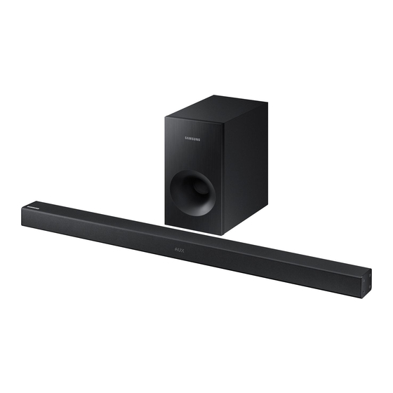
Wireless Audio – Soundbar
(Active Speaker System)
HW-K360
Refer to the service manual in the GSPN (see the rear cover) for more information.
Wireless Audio –
Soundbar (Active
Speaker System)
Model Name
Model Code
MANUAL
1. Precaution
2. Product Specification
3. Disassembly & Reassembly
4. Troubleshooting
5. PCB Diagram
6. Schematic Diagram
HW-K360
HW-K360/ZA
Contents
Advertisement
Table of Contents

Related Manuals for Samsung HW-K360


Summary of Contents for Samsung HW-K360
- Page 1 Wireless Audio – Soundbar (Active Speaker System) Model Name HW-K360 Model Code HW-K360/ZA SERVICE MANUAL Wireless Audio – Soundbar Contents (Active Speaker System) 1. Precaution 2. Product Specification 3. Disassembly & Reassembly 4. Troubleshooting 5. PCB Diagram HW-K360 6. Schematic Diagram...
-
Page 2: Table Of Contents
Test Point Wave Form ....................5 − 10 5.7. JACK PCB Bottom ........................5 − 11 5.7.1. Pin Connection ......................5 − 12 Schematic Diagram ........................... 6 − 1 6.1. Overall Block Diagram ......................6 − 1 Copyright© 1995-2016 SAMSUNG. All rights reserved. - Page 3 MAIN-2..........................6 − 3 6.4. MAIN-3..........................6 − 4 6.5. MAIN-4..........................6 − 5 6.6. VFD............................6 − 6 6.7. JACK ............................ 6 − 7 6.7.1. Test Point Wave Form ....................6 − 8 Copyright© 1995-2016 SAMSUNG. All rights reserved.
-
Page 4: Precaution
TES T ALL EXPO S ED METAL SU RFACES 2-WIRE CORD ALSO TES T WITH PLUG REVER S ED (US ING AC EARTH ADAPTER P LUG GROUND AS R EQ UIRED) Figure 1.1 AC Leakage Test Copyright© 1995-2016 SAMSUNG. All rights reserved. - Page 5 A replacement part that does not have the same safety characteristics as the original might create shock, fire or other hazards. Copyright© 1995-2016 SAMSUNG. All rights reserved.
-
Page 6: Servicing Precautions
CAUTION First read the “Safety Precautions” section of this manual. If some unforeseen circumstance creates a conflict between the servicing and safety precautions, always follow the safety precautions. Copyright© 1995-2016 SAMSUNG. All rights reserved. -
Page 7: Precautions For Electrostatically Sensitive Devices (Esds)
8) Minimize body motions when handling unpackaged replacement ESDs. Motions such as brushing clothes together, or lifting a foot from a carpeted floor can generate enough static electricity to damage an ESD. Copyright© 1995-2016 SAMSUNG. All rights reserved. -
Page 8: Installation Precautions
5) Installing the product in a special place like below rather than normal environment may cause serious quality concerns due to its special conditions. If this is the case, make sure to contact a local Samsung service center before installing the product. -
Page 9: Product Specification
2. Product Specification 2.1. Product Feature ■ HW-K360 • 130 W (Front 35 W x 2 + Woofer 60 W) • 2.1CH, System • 1 analog / 1 optical • USB Host, Bluetooth • Wireless Subwoofer Copyright© 1995-2016 SAMSUNG. All rights reserved. -
Page 10: Specifications
• S/N ratio, distortion, separation and usable sensitivity are based on measurement using AES (Audio Engineering Society) guidelines. • Samsung Electronics Co., Ltd reserves the right to change the specifications without notice. • Weight and dimensions are approximate. Copyright© 1995-2016 SAMSUNG. All rights reserved. -
Page 11: Specifications Analysis
Headphone Jack USB Jack Jack Type USB 2.0 Micro USB Type B Plug (Male) USB 2.0 Type A Jack (Female) Type (Sat/Tallboy) Sealed Enclosure Sealed Enclosure Speaker Active (Powered) S/W Wireless Active Wireless Active Copyright© 1995-2016 SAMSUNG. All rights reserved. - Page 12 2. Product Specification O : Feature Included X : Not Included Copyright© 1995-2016 SAMSUNG. All rights reserved.
-
Page 13: Accessories
DC Adapter BN44-00835A Optical cable AH39-00779A Local Samsung Dealer Wall Mount Guide AH63-04369A Holder-screw 1 : 2EA AH61-04110A Holder-screw 2 : 2EA 6001–001961 L : AH61-04106A Bracket-Wall Mount R : AH61-04114A User Manual AH68-02608A Copyright© 1995-2016 SAMSUNG. All rights reserved. -
Page 14: Disassembly & Reassembly
Remove the COVER-JACK and take the PBA out, Then disconnect wire 2ea,remove the main Unfasten 1 screws on the VFD. and remove VFD form the bracket Unfasten 2 screw on the wireless and BT module Copyright© 1995-2016 SAMSUNG. All rights reserved. -
Page 15: Troubleshooting
4. Troubleshooting 4. Troubleshooting 4.1. Checkpoints by Error Mode Oscilloscope Setting Values Voltage/DIV 1 V/div TIME/DIV 500 ms/div Copyright© 1995-2016 SAMSUNG. All rights reserved. -
Page 16: No Power
#62 Re pla ce the Micom (UIC1). of the UIC1 whe n Ma in P CB powe r is turne d on. Ye s Cha nge the MAIN PC B. Copyright© 1995-2016 SAMSUNG. All rights reserved. -
Page 17: No Sound Output
Change the MAIN PCB. ACN1,ACN2 speaker out put s igna l. Re fe r to wa ve pa tte rn ima ge of Fig. 4-3. Ye s Cha nge S pe a ke r L, R. Copyright© 1995-2016 SAMSUNG. All rights reserved. - Page 18 DATA_MICOM OUT/CRE SCENDO IN CST_MA K CST_MA K D_MO_CI D_MO_CI 100 OHM 1/16 W 100 OHM 1/16W CRESCENDO_STROBE/MICOM_ACK CRESCENDO_STROBE/MICOM_ACK R3031 R3031 100 OHM 1/16 W 100 OHM 1/16W CII_RES ET CII_RES ET * 6.4. MAIN-3 <Fig. 4-1> Copyright© 1995-2016 SAMSUNG. All rights reserved.
- Page 19 1/10W /OTW /OTW OUT_D OUT_D /CLIP /CLIP OUT_D OUT_D 100OHM 100OHM BST_C BST_C C124 C124 GVDD_CD GVDD_CD BST_D BST_D 33 NF 50V 33 NF 50V FL/FR FL/FR DGND DGND * 6.6. MAIN-5 <Fig. 4-2> Copyright© 1995-2016 SAMSUNG. All rights reserved.
- Page 20 SPK _FL+ SPK _FL+ L(+) L(+) L1(+) L1(+) MGND2 MGND2 SP_ GND SP_ GND MGND1 MGND1 SP1 _GND SP1 _GND L(-) L(-) L1(-) L1(-) ACN1 ACN1 SMW200-H03G SMW200-H03G DGND DGND * 6.6. MAIN-5 <Fig. 4-3> Copyright© 1995-2016 SAMSUNG. All rights reserved.
-
Page 21: Measures To Be Taken When The Protection Circuit Operates
If there is a large difference than the value listed above then the AMP PCB has a problem. ET CH AS S I S P E AK E R O U T P U T Copyright© 1995-2016 SAMSUNG. All rights reserved. -
Page 22: Initialization & Update
2) Turn the unit off. 3) Press the “Sound Effectl” button for 5 seconds in the remote control. 4) OLED display a version like below. (Micom → DSP → HDMI → Tx → Rx → Touch) Copyright© 1995-2016 SAMSUNG. All rights reserved. - Page 23 4. Troubleshooting D 050 WGM050 Copyright© 1995-2016 SAMSUNG. All rights reserved.
-
Page 24: Usb Update Procedure
Cas e 1 : Micom Upda te . UP D UP D DONE Cas e 2 : DS P Upda te . DONE 1 00% Cas e 3 : Wireles s U pda te. DONE 1 00% 4-10 Copyright© 1995-2016 SAMSUNG. All rights reserved. -
Page 25: Pcb Diagram
5. PCB Diagram 5. PCB Diagram 5.1. Wiring Diagram Copyright© 1995-2016 SAMSUNG. All rights reserved. -
Page 26: Main Pcb Top
5. PCB Diagram 5.2. MAIN PCB Top IC 1 C N 4 C N 2 0 1 IC 1 CN1 4 C N 3 0 0 4 C N 1 0 2 Copyright© 1995-2016 SAMSUNG. All rights reserved. -
Page 27: Pin Connection
KEY CONTROL Pin No. Signal KEY_PWR KEY_FUNC KEY_VOL+ KEY_VOL- 5) ACN1 SPEAKER L Pin No. Signal FULL RANGE L+ FULL RANGE L- 6) ACN2 SPEAKER R Pin No. Signal FULL RANGE R+ FULL RANGE R- Copyright© 1995-2016 SAMSUNG. All rights reserved. -
Page 28: Main Pcb Bottom
5. PCB Diagram 5.3. MAIN PCB Bottom Copyright© 1995-2016 SAMSUNG. All rights reserved. -
Page 29: Pin Connection
5.3.1. Pin Connection 2) CN3003 BT Module Control Pin No. Signal BT_RST D3.3V BT_TX BT_RX DGND EP_SCL EP_SDA DGND 3) WCN1 Wireless Module Control Pin No. Signal W_SDATA X_SDATA LRCK W_SDA W_CLK DARR_RST D+5V_PW D+5V_PW Copyright© 1995-2016 SAMSUNG. All rights reserved. -
Page 30: Vfd Pcb Top
5. PCB Diagram 5.4. VFD PCB Top Copyright© 1995-2016 SAMSUNG. All rights reserved. -
Page 31: Vfd Pcb Bottom
5. PCB Diagram 5.5. VFD PCB Bottom C N 1 Copyright© 1995-2016 SAMSUNG. All rights reserved. -
Page 32: Jack Pcb Top
5. PCB Diagram 5.6. JACK PCB Top AN 4 0 0 AU X1 Copyright© 1995-2016 SAMSUNG. All rights reserved. -
Page 33: Pin Connection
3) AN400 AUX Signal Optical Signal Touch CON Pin No. Signal Pin No. Signal Pin No. Signal DGND HM3.3V HDGND AUX_L HDGND HDGND OPTICAL_0_H K_PWR AUX_R K_FUNC DGND K_VOL- AUX_SENS_H K_VOL+ DGND HDGND HDGND Copyright© 1995-2016 SAMSUNG. All rights reserved. -
Page 34: Test Point Wave Form
5. PCB Diagram 5.6.2. Test Point Wave Form 5-10 Copyright© 1995-2016 SAMSUNG. All rights reserved. -
Page 35: Jack Pcb Bottom
5. PCB Diagram 5.7. JACK PCB Bottom IC 100 Copyright© 1995-2016 SAMSUNG. All rights reserved. 5-11... -
Page 36: Pin Connection
5.7.1. Pin Connection 1) HCN4 MAIN ASSY Pin No. Signal DGND DGND DGND DGND DGND DGND DGND DGND DGND DGND DGND DGND DGND AUX_L AUX_SENS DGND T_SDA AUX_R T_SCL DGND T_RST SPDIF_IN1 M3.3V 5-12 Copyright© 1995-2016 SAMSUNG. All rights reserved. -
Page 37: Schematic Diagram
DSP(SDP1207) implement DSP AUDIO DECODING function by I2S. • Power On/Off by Micom port is possible. • Function and sound field can be controlled by remote controller and keys. • The active subwoofer operate with wireless system. Copyright© 1995-2016 SAMSUNG. All rights reserved. -
Page 38: Main-1
CHANGE T O 3722-0 03205 CHANGE T O 3722-0 03205 PVDD+19V_PW PVDD+19V_PW FGND1 FGND1 +19V4 +19V4 MGND1 MGND1 +19V3 +19V3 451005 451005 +19V1 +19V1 +19V2 +19V2 MGND2 MGND2 FGND2 FGND2 FGND3 FGND3 FGND4 FGND4 DGND_GND DGND_GND Copyright© 1995-2016 SAMSUNG. All rights reserved. -
Page 39: Main-2
131127 10N F 16V -> 220UF 16V 131127 10N F 16V -> 220UF 16V AABD2 AABD2 0.0 1OHM 0.0 1OHM AUX1 AUX1 FOR USB3.0 PROBLEM FOR USB3.0 PROBLEM HAGND HAGND DGND_GND DGND_GND HAGND HAGND Copyright© 1995-2016 SAMSUNG. All rights reserved. -
Page 40: Main-3
OPT_DET1 OPT_DET1 OPC2 OPC2 OPR4 OPR4 OPR1 OPR1 270 OHM 270 OHM 100 NF 100 NF 4.7 KOHM 4.7 KOHM 1/16W 1/16W 0OHM 0OHM 1/16W 1/16W SBT42 SBT42 SPDIF_IN1 SPDIF_IN1 OPQ1 OPQ1 DGND_GND DGND_GND Copyright© 1995-2016 SAMSUNG. All rights reserved. -
Page 41: Main-4
C3023 C3023 W_SDATA W_SDATA 10KOHM 10KOHM 100NF 16V 100NF 16V 33OHM 1/16W 33OH M 1/16W R3069 R3069 X_SDATA X_SDATA 33OHM 33OHM 1/16W 1/16W AMP_DATA0 AMP_DATA0 R3037 R3037 DGND_GND DGND_GND 33OHM 1/16W 33OH M 1/16W Copyright© 1995-2016 SAMSUNG. All rights reserved. -
Page 42: Vfd
1/10W 1/10W FC2 20 FC2 20 C1006 C1006 10UF 10UF FC51 FC51 FC53 FC53 FR220 FR220 FR1 90 FR1 90 10KOHM 10KOHM 10KOHM 10KOHM FC52 FC52 DGND DGND DGND DGND DGND DGND DGND DGND Copyright© 1995-2016 SAMSUNG. All rights reserved. -
Page 43: Jack
T_RS T T_RS T OPTICAL_0_H OPTICAL_0_H T_RS T T_RS T AUX_L AUX_L T_SCL T_SCL AUX_R AUX_R H3.3V H3.3V T_SDA T_SDA OPTIC AL_0 OPTIC AL_0 HD_GN D HD_GN D HA_GND HA_GND HDGND HDGND HDGND HDGND Copyright© 1995-2016 SAMSUNG. All rights reserved. -
Page 44: Test Point Wave Form
6. Schematic Diagram 6.7.1. Test Point Wave Form Copyright© 1995-2016 SAMSUNG. All rights reserved. - Page 45 E.Asia, W.Asia, https://gspn2.samsungcsportal.com China, Japan N.America, S.America https://gspn3.samsungcsportal.com This Service Manual is a property of Samsung Electronics Co.,Ltd. © 2016 Samsung Electronics Co.,Ltd. Any unauthorized use of Manual can be punished under All rights reserved. applicable International and/or domestic law.
Need help?
Do you have a question about the HW-K360 and is the answer not in the manual?
Questions and answers