Table of Contents
Advertisement
Available languages
Available languages
INSTALLATION & INSTRUCTION
MANUAL FOR
HEAT PUMP
WITH WIFI MODULE
BP-50HS-A
BP-85HS-A
BP-100HS-A
BP-120HS-A
BP-140HS-A
The illustrations shown in this manual may not always correspond to a specific design;
their purpose is to help better understand the text.
The manufacturer and supplier reserve the right to make changes to the product
without obligation update this Installation and Operation Guide.
EN
3EXX0689-3EXB0603-3EXB0604-3EXB0605-3EXB0606
INSTRUCTIONS FOR USE AND MAINTENANCE
CZ-09/2021-No.:710-C
Advertisement
Chapters
Table of Contents

Subscribe to Our Youtube Channel
Related Manuals for Mountfield Azuro BP-50HS-A


Summary of Contents for Mountfield Azuro BP-50HS-A
- Page 1 INSTALLATION & INSTRUCTION MANUAL FOR HEAT PUMP WITH WIFI MODULE BP-50HS-A BP-85HS-A BP-100HS-A BP-120HS-A BP-140HS-A The illustrations shown in this manual may not always correspond to a specific design; their purpose is to help better understand the text. The manufacturer and supplier reserve the right to make changes to the product without obligation update this Installation and Operation Guide.
-
Page 2: Table Of Contents
TABLE OF CONTENTS INTRODUCTION Heat Pump Applications Principle of Heat Pump Operation Check of Delivery SAFETY INSTRUCTIONS EQUIPMENT DESCRIPTION AND TECHNICAL SPECIFICATION Technical Data Pool Water Parameters Heat Pump Dimensions Description of Basic Parts Safety and Control Systems HEAT PUMP INSTALLATION AND CONNECTION Site Selection Heat Pump Installation Electrical Connection... -
Page 3: Introduction
INTRODUCTION Thanks for you have chosen our heat pump. The heat pump is manufactured in compliance with strict technical standards in order to provide our customers with excellent quality and adequate reliability. These instructions for use contain all information required for installing the heat pump, putting it into operation and performing its maintenance. Read the instructions carefully before commencing any handling or maintenance. -
Page 4: Safety Instructions
SAFETY INSTRUCTIONS CAUTION: The equipment contains electrical components under voltage. The equipment may be opened only by an electrician of appropriate technical qualifi cation. There is a danger of electrical accident!! (a) The equipment is not intended for use by persons having reduced physical, sensory or mental ability (including children) without being supervised and instructed by a responsible adult, for use by persons not well acquainted with the operation of the equipment within the scope hereof, persons whose ability of immediate response is reduced due to consumption of drugs and/or narcotics, etc. -
Page 5: Heat Pump Dimensions
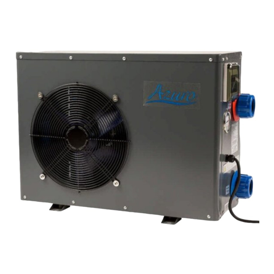
HEAT PUMP DIMENSIONS BP-50HS-A BP-85HS-A BP-100HS-A BP-120HS-A BP-140HS-A 517,5 Note: The dimensions are given in mm. WARNING: The manufacturer reserves the right to make such product modifi cations that will not infl uence its essential properties. DESCRIPTION OF BASIC PARTS 1 –... -
Page 6: Safety And Control Systems
SAFETY AND CONTROL SYSTEMS The heating pump is fi tted with the following systems: Heat pump control based on temperature: The temperature sensor of evaporator triggers the defrosting process. The ambient (outdoor) temperature sensor provides for switching the heat pump OFF, if the temperature drops below 7 °C (factory setting). The normal operation will resume as soon as the ambient temperature has risen to -5 °C (factory setting). -
Page 7: Heat Pump Installation
(d) The air outlet should not be directed to areas, where the increased circulation of cold air may be bothering (windows, terrace, etc.). The air outlet should not face against the direction of prevailing winds. (e) The equipment distance from the pool edge shall not be shorter than 3.5 m. It is recommended to install the heat pump at the distance of 7 m from the pool provided that the overall length of interconnecting pipe system will not exceed 30 m. -
Page 8: Electrical Connection
ELECTRICAL CONNECTION 4.3.1 CONNECTION TO THE MAINS IMPORTANT: The heat pump is supplied with a power supply cable. Socket installation shall meet the requirements of the ČSN 33 2000 standard, including adequate protection and installation of a residual-current circuit breaker (RCCB) of the actuating current not exceeding 30 mA. The use of a double socket with common switching (by a switch or a timer) is recommended. -
Page 9: Heat Pump Switching On And Off
HEAT PUMP SWITCHING ON AND OFF Connect the equipment to the mains (switch the circuit breaker on). key. In operation the display shows the temperature of water at the heat exchanger inlet and the heating After switching the system on, press the mode symbol. - Page 10 Notes on the table of operating parameters: Parameter H0 - H5 – automatic defrost setting If the temperature sensor detects a temperature lower than the temperature set by parameter H3 on the evaporator, which it checks at regular intervals given by parameter H0, the device switches to defrost mode and ends this mode after reaching one of the values set in parameters H1 and H2.
-
Page 11: Change Of Operating Mode
CHANGE OF OPERATING MODE The heat pump has 3 operating modes - heating, cooling and automatic mode. If you want to change the operating mode, briefly press the button. The operating mode changes, the corresponding signal changes on the display, and if the compressor is running, it stops. The compressor will start again after the safety time delay has elapsed (if the conditions for operation in the newly selected mode are met). -
Page 12: Control Panel Locking
CONTROL PANEL LOCKING Press and hold pressed the keys SET and ◄ simultaneously for about 5 seconds. This operation will lock the control panel. Unlock the panel in the same way. EQUIPMENT APPLICATION AND OPERATION OPERATING INSTRUCTIONS IMPORTANT: In order the heat pump to heat the pool the fi ltration pump has to operate and water must fl ow through the heat exchanger. Never switch the heat pump on if dry and the fi... -
Page 13: Water Condensation
WATER CONDENSATION Lower temperatures of the evaporator during the heat pump operation are the cause of air moisture condensation on evaporator lamellae and condensate formation. If the relative air humidity is very high, as much as a few litres per hour can be produced. This water will fl ow down over the lamellae into the space of cabinet bottom and drains away through a plastic fi... -
Page 14: Remarks On Heat Pump Operation
This state is due to the following causes: COOLING MODE Too high water fl ow rate. Open the bypass valve to reduce HEATING MODE water fl ow rate and increase thereby the heat transfer Insuffi cient water fl ow rate. Close the bypass from water to coolant. -
Page 15: Maintenance And Inspection
Remote device or control key Activity Display Heat pump response of heat pump The HP stops immediately Stop Press the key and stays in the standby state. Pull out the supply cable plug from the mains socket The heat pump gets Switching OFF or switch OFF the circuit completely switched OFF. -
Page 16: Error Messages And Troubleshooting
ERROR MESSAGES AND TROUBLESHOOTING Displayed error message and related Putting it right, other possible Component Possible cause equipment failure causes and solutions Check the wires and connections, Compressor and blower Water temperature Sensor signal wire or supply wire is PP 1 replace defective ones. -
Page 17: Wifi Module
WiFi module MANUAL of WiFi module Boost CORE 1. APP installation iOS version Please enter APP Store and search “Boost CORE”. Then download and install Android version Please enter Google Market and search “Boost CORE”. Then download and install it. - Page 18 2. Register and login 1) When the APP is opened, the “Agreement” will show up. It will then go to the “Login Screen” after you agree. Then you can input your Username and Password to login. If you haven’t registered an account yet, please follow below steps to register.
- Page 19 b) Below screen will show up. Please select your country and input your mobile number or Email address. Then tick the agreement and click “Get Validation Code”, you will receive a “Validation Code” by SMS/Email and screen will come to below.
- Page 20 Please input the “Validation Code” and set your password. Then click the “Done” to finish the register. c) Then choose “Log In” and input the Username and Password to login.
- Page 21 2) If you forget the password, please follow below steps to reset it. a) Press “Forgot password” to reset the password. b) Return to the step 1)-b).
- Page 22 3. Pairing the heat pump It is necessary to pair your new heat pump to your smart phone, then you can control the heat pump through your smart phone. Please make sure your smart phone is connected with your Wi-Fi router, and the Wi-Fi signal can be receipted by the heat pump clearly.
- Page 23 3) This APP is supported only on 2.4GHz Wi-Fi channel. Make sure the Wi-Fi setting is right, or you need to change it manually. Click “X” to back to Add Manually and choose any device. Then input your Wi-Fi password and press “Next”. If below warning appear, please click “CONTINUE”.
- Page 25 4) Wait for the pairing, it will take about one minute. 5) After successfully pairing, the APP will turn to “MyDevice” list. Choose “Boost Core” and you can start to control the heat pump.
- Page 26 4. Operation screen Power OFF Power ON “-” and “+” symbols are for target temperature setting. Press the “ ” symbol to turn on/off the heat pump. You can shift the Cooling/Heating/Auto Mode by “Mode” symbol. “Timer” and temperature information are in the “Setting”...
- Page 27 5. Timer setting 1)This APP can also set timer for power ON/OFF automatically. You can press “Timer” into the timer schedule. 2)Press “Add” to set new timers.
- Page 28 3)You can set the time by rolling it. 4)Adjust each setting as you wish, press “Save” to save it.
- Page 29 INSTALLATIONS UND BEDIENUNGSANLEITUNG FÜR WÄRMEPUMPE MIT WIFI-MODUL BP-50HS-A BP-85HS-A BP-100HS-A BP-120HS-A BP-140HS-A Die in diesem Handbuch gezeigte Bilder entsprechen möglicherweise nicht immer einem bestimmten Design. Der Zweck ist es, den Text besser zu verstehen. Der Hersteller und Lieferant behält sich das Recht vor, Änderungen am Produkt vorzunehmen, ohne diese Installations- und Bedienungsanleitung zu aktualisieren.
- Page 30 INHALT EINLEITUNG Verwendung der Wärmepumpe Funktionsprinzip der Wärmepumpe Kontrolle der Verpackung SICHERHEITSHINWEISE BESCHREIBUNG DER ANLAGE UND TECHNISCHE SPEZIFIKATION Technische Daten Poolwasser-Parameter Maße der Wärmepumpe Beschreibung der Grundteile Sicherheits- und Steuerungssysteme INSTALLATION UND ANSCHLUSS DER WÄRMEPUMPE Wahl des Aufstellortes Installation der Wärmepumpe Elektroanschluss 4.3.1 Anschluss in Steckdose...
-
Page 31: Einleitung
EINLEITUNG Herzlichen Dank, dass Sie sich für unsere Wärmepumpe entschieden haben. Die Wärmepumpe wird nach strengen Normen hergestellt, um unseren Kunden die gewünschte Qualität und Zuverlässigkeit zu sichern. Diese Bedienungsanleitung enthält alle notwendigen Informationen zur Installierung, Inbetriebsetzung und Wartung der Anlage. Bevor Sie mit der Anlage manipulieren oder eine Wartung jeglicher Art durchführen, lesen Sie bitte diese Bedienungsanleitung sorgfältig durch. -
Page 32: Sicherheitshinweise
SICHERHEITSHINWEISE ACHTUNG: Die Anlage enthält elektrische Teile unter Spannung. Die Anlage darf nur eine Person mit entsprechender elektrotechnischer Qualifi kation öff nen. Unfallgefahr durch Stromschlag. (a) Diese Anlage ist nicht dafür bestimmt, durch Personen (einschließlich Kinder) mit eingeschränkten physischen, sensorischen oder geistigen Fähigkeiten benutzt zu werden, es sei denn, sie werden durch eine für ihre Sicherheit zuständige Person beaufsichtigt oder erhielten von ihr Anweisungen, wie die Anlage zu benutzen ist;... -
Page 33: Maße Der Wärmepumpe
MAßE DER WÄRMEPUMPE BP-50HS-A BP-85HS-A BP-100HS-A BP-120HS-A BP-140HS-A 517,5 Bemerkung: Maße werden in Millimetern angegeben. HINWEIS: Der Hersteller behält sich das Recht vor, Produktänderungen durchzuführen, die keine Einwirkung auf dessen unerlässliche Eigenschaften haben werden. BESCHREIBUNG DER GRUNDTEILE 1 – Schutzgitter des Ventilators (Luftaustritt) 2 –... -
Page 34: Sicherheits- Und Steuerungssysteme
SICHERHEITS UND STEUERUNGSSYSTEME Die Wärmepumpe ist mit folgenden Systemen ausgestattet: Betriebsteuerung der Wärmepumpe aufgrund der Temperatur: Temperatursensor des Verdampfers löst den Abtauvorgang aus. Außentemperatursensor sorgt für das Ausschalten der Wärmepumpe, wenn die Temperatur unter -7 °C (Produktionseinstellung) sinkt. Der normale Betriebsmodus wird wieder aufgenommen, wenn die Außentemperatur auf -5 °C (Werkseinstellung) steigt. -
Page 35: Installation Der Wärmepumpe
(d) Der Luftaustritt sollte nicht an Stellen gerichtet werden, wo die Kaltluftströmung eine Belästigung darstellen könnte (Fenster, Terrasse, ...). Den Luftaustritt orientieren Sie nicht gegen die Richtung der vorherrschenden Winde. (e) Der Abstand der Anlage vom Schwimmbeckenrand darf nicht geringer als 3,5 m sein. Es wird empfohlen die Wärmepumpe im Abstand von 7 m vom Pool so aufzustellen, dass die Gesamtlänge der Verbindungsrohrleitung nicht 30 m überschreitet. -
Page 36: Elektroanschluss
ELEKTROANSCHLUSS 4.3.1 ANSCHLUSS IN STECKDOSE ohne WICHTIG: Die Wärmepumpe wird Zuleitungskabel geliefert. Die Installation der Steckdose muss den Anforderungen ČSN 33 2000 entsprechen, einschl. entsprechender Sicherung und Verwendung vom Fehlerstromschutzschalter mit Auslösestrom bis 30 mA. Es wird empfohlen eine Zweifachsteckdose mit gemeinsamer Schaltung (Schalter oder Zeitschaltuhr) zu verwenden. Einschalten und Ausschalten der Wärmepumpe ist in Kapiteln 5 und 6 beschrieben. -
Page 37: Ein- Und Ausschalten Der Wärmepumpe
EIN UND AUSSCHALTEN DER WÄRMEPUMPE Schließen Sie die Anlage an das Netzwerk an (schalten Sie die Sicherung ein). Drücken Sie zum Einschalten der Anlage. Während des Betriebes zeigt das Display die Wassertemperatur am Eintritt in den Wärmetauscher und Hei- zmodus an. Drücken Sie zum Ausschalten der Anlage. - Page 38 Hinweise zur Tabelle der Betriebsparameter: Parameter H0 - H5 – automatische Abtaueinstellung Wenn der Temperatursensor eine niedrigere Temperatur als die mit Parameter H3 am Verdampfer eingestellte Temperatur erkennt, die er in regelmäßigen Abständen durch Parameter H0 überprüft, wechselt das Gerät in den Abtaumodus und beendet diesen Modus nach Erreichen eines der in Parameter H1 eingestellten Werte und H2.
-
Page 39: Änderung Des Betriebsmodus
ÄNDERUNG DES BETRIEBSMODUS Die Wärmepumpe hat 3 Betriebsarten - Heizen, Kühlen und Automatikbetrieb. Wenn Sie die Betriebsart ändern möchten, drücken Sie kurz die Taste . Die Betriebsart ändert sich, das entsprechende Signal im Display ändert sich und wenn der Kompressor läuft, stoppt er. Der Verdichter startet nach Ablauf der Sicherheitszeitverzögerung wieder (wenn die Bedingungen für den Betrieb im neu gewählten Modus erfüllt sind). -
Page 40: Sperre Des Steuerpaneels
SPERRE DES STEUERPANEELS Durch Drücken und Halten der Tasten SET und ◄ gleichzeitig für die Dauer von 5s wird das Steuerpaneel geschlossen. Die Entriegelung des Paneels wird auf die gleiche Weise durchgeführt. VERWENDUNG UND BETRIEB DER ANLAGE BETRIEBSANWEISUNGEN WICHTIG: Damit die Wärmepumpe den Pool beheizt, muss die Filtrationspumpe im Betrieb sein und das Wasser durch den Wärmetauscher strömen. Die Wärmepumpe niemals einschalten, wenn sich diese ohne Wasser befindet und die Filtrationsanlage nicht im Betrieb ist. -
Page 41: Wasserkondensation
WASSERKONDENSATION Eine niedrigere Temperatur des Verdampfers während des Betriebes der Wärmepumpe ist die Ursache für Feuchtigkeit an Lamellen des Verdampfers und für die Entstehung vom Kondenswasser. Wenn die relative Feuchtigkeit sehr hoch ist, kann dies einige Liter Kondenswasser in der Stunde zu Folge haben. Das Wasser läuft an den Lamellen auf den Boden des Gehäuses und durch die Kunststoff... -
Page 42: Hinweise Zum Betrieb Der Wärmepumpe
Ursachen dieses Zustandes sind folgende: MODUS KÜHLUNG MODUS AUFHEIZUNG Zu hoher Wasserdurchfl uss. Zur Reduzierung des Wasserdurchfl usses und damit Erhöhung des Wärmeaustauschs Unzureichender Wasserdurchfl uss. Zur Erhöhung des Wasser → Kühlmittel öff nen Sie Bypass-Ventil. Wärmeaustauschs Kühlmittel → Wasser schließen Sie Unzureichende Luftströmung. -
Page 43: Wartung Und Kontrolle
Externe Anlage oder Steuertaste der Wirkung Vorgang Display Wärmepumpe der Wärmepumpe Die Wärmepumpe stoppt Drücken Sie Taste Stop sofort und bleibt im für 3 sec. Standby Modus. Ziehen Sie den Stecker aus der Steckdose; bei festem Komplettes Ausschalten Ausschalten Anschluss schalten Sie den der Wärmepumpe. -
Page 44: Fehlermeldungen Und Deren Beseitigung
FEHLERMELDUNGEN UND DEREN BESEITIGUNG Angezeigte Fehlermeldung und Beseitigung Weitere mögliche Komponente Mögliche Ursache Betriebszustand der Wärmepumpe Ursache und Lösung Sensor, Leitungen und Anschlüsse Es ist zum Stillstand des Leitung zum Sensor unterbrochen, kontrollieren. Mangelhafte Teile PP 1 Kompressors und Ventilators Wassertemperatursensor unterbrochene Stromversorgung oder austauschen. -
Page 45: Wifi-Modul
WiFi-modul HANDBUCH von WiFi-Module Boost CORE 1. APP installation iOS version Bitte betreten Sie den APP Store und suchen Sie nach „Boost CORE“. Laden Sie es dann herunter und installieren Sie es. Android version Bitte betreten Sie den Google Market und suchen Sie nach „Boost CORE“. Laden Sie es dann herunter und installieren Sie es. - Page 46 2. Registrieren und einloggen 1) Wenn die APP geöffnet wird, wird die „Vereinbarung“ angezeigt. Es wird dann zum „Anmeldebildschirm“ gehen, nachdem Sie zugestimmt haben. Dann können Sie Ihren Benutzernamen und Ihr Passwort eingeben, um sich anzumelden. Wenn Sie noch kein Konto registriert haben, befolgen Sie bitte die folgenden Schritte, um sich zu registrieren.
- Page 47 b) Der folgende Bildschirm wird angezeigt. Bitte wählen Sie Ihr Land und geben Sie Ihre Handynummer oder E-Mail- Adresse ein. Dann kreuzen Sie die Vereinbarung an und klicken Sie auf „Validierungscode abrufen“, Sie erhalten einen „Validierungscode“ per SMS/E- Mail und der Bildschirm wird unten angezeigt.
- Page 48 Bitte geben Sie den „Validation Code“ ein und legen Sie Ihr Passwort fest. Klicken Sie anschließend auf „Fertig“, um die Registrierung abzuschließen. c) Wählen Sie dann „Anmelden“ und geben Sie den Benutzernamen und das Passwort ein, um sich anzumelden.
- Page 49 2) Wenn Sie das Passwort vergessen, befolgen Sie bitte die folgenden Schritte, um es zurückzusetzen. a) Drücken Sie „Passwort vergessen“, um das Passwort zurückzusetzen. b) Kehren Sie zu Schritt 1)-b) zurück.
- Page 50 3. Kopplung der Wärmepumpe Sie müssen Ihre neue Wärmepumpe mit Ihrem Smartphone koppeln, dann können Sie die Wärmepumpe über Ihr Smartphone steuern. Bitte stellen Sie sicher, dass Ihr Smartphone mit Ihrem WLAN-Router verbunden ist und das WLAN-Signal von der Wärmepumpe deutlich empfangen werden kann. 1) Schalten Sie die Wärmepumpe ein.
- Page 51 3) Diese APP wird nur auf dem 2,4-GHz-WLAN-Kanal unterstützt. Stellen Sie sicher, dass die WLAN-Einstellung richtig ist, oder Sie müssen sie manuell ändern. Klicken Sie auf „X“, um zu „Manuell hinzufügen“ zurückzukehren und ein beliebiges Gerät auszuwählen. Geben Sie dann Ihr WLAN-Passwort ein und klicken Sie auf „Weiter“. Wenn die folgende Warnung erscheint, klicken Sie bitte auf „WEITER“.
- Page 53 4) Warten Sie auf das Pairing, es dauert etwa eine Minute. 5) Nach erfolgreichem Pairing wechselt die APP zur Liste „MyDevice“. Wählen Sie „Boost Core“ und Sie können Beginnen Sie mit der Steuerung der Wärmepumpe.
- Page 54 4. Betriebsbildschirm Einschalten Ausschalten Die Symbole „-“ und „+“ stehen für die Einstellung der Zieltemperatur. Drücken Sie das Symbol „ “, um die Wärmepumpe ein-/auszuschalten. Sie können den Kühl-/Heiz-/Auto-Modus durch das „Modus“-Symbol wahlen. „Timer“ und Temperaturinformationen sind in der „Einstellung“...
- Page 55 5. Timer Einstellung 1)Diese APP kann auch den Timer für das Ein- und Ausschalten automatisch einstellen. Sie können „Timer“ in den Timer-Zeitplan drücken. 2)Drücken Sie „Hinzufügen“, um neue Timer einzustellen.
- Page 56 3)Sie können die Zeit durch Rollen einstellen. 4)Passen Sie jede Einstellung nach Ihren Wünschen an, drücken Sie auf „Speichern“, um sie zu speichern.
Need help?
Do you have a question about the Azuro BP-50HS-A and is the answer not in the manual?
Questions and answers
Как задать требуемую температуру воды?