
Related Manuals for Kleinn Air Horns X3-KIT


Summary of Contents for Kleinn Air Horns X3-KIT
- Page 1 X3-KIT INSTALLATION MANUAL REV: BETA (4/25/2019) © Kleinn Air Horns 2019, All rights reserved. PO Box 91278 Tucson, AZ 85752 Phone: (520) 579-1531 Web: www.Kleinn.com...
- Page 2 X3-KIT Installation and Operation Manual This digital PDF is interactive. Please save ink and paper… Open interactive manual using Adobe Reader ® PC, MAC, and all smart devices Go to Table of Contents PG 2/40 REV: BETA (4/25/2019)
-
Page 3: Table Of Contents
X3-KIT Installation and Operation Manual Table of Contents LIST OF FIGURES ..............................5 How to Use this Manual .............................6 2.1. Interactive Manual using Adobe Reader ....................6 2.2. Your Kit SKU Number and this Manual .......................6 2.3. Illustration/Photo Details and Orientation ....................6 Safety First ................................7... - Page 4 X3-KIT Installation and Operation Manual 8.7. Air Compressor Bracket - Installation ...................... 26 8.8. Air Compressor - Installation ........................28 8.9. Air Horn - Installation ..........................30 8.10. Connect Remote Quick Connect Kit to Vehicle ..................34 On-Vehicle Electrical Installation ........................35 9.1.
-
Page 5: List Of Figures
X3-KIT Installation and Operation Manual 1. LIST OF FIGURES Figure 1 – Top View Showing Kit Layout (2018 X3 2 Door Shown) ................. 10 Figure 2 – Passenger Rear Fender Removal (fasteners on top of fender) .............. 19 Figure 3 – Passenger Rear Fender Removal (fasteners behind door and fender) ..........19 Figure 4 –... -
Page 6: How To Use This Manual
Your Kit SKU Number and this Manual This manual covers installation, testing, and operation of following SKU part numbers 2.2.1. X3-KIT (i.e., 102b Train Horn with On-Board Air System) 2.2.2. X3-OBA (i.e., On-Board Air System) NOTE: Illustrations and pictures contained herein may represent only one kit part number. Where critical differences exist between kits (i.e., different parts, orientation, mounting points, etc.), additional... -
Page 7: Safety First
X3-KIT Installation and Operation Manual 3. Safety First Read manual thoroughly before starting installation of this kit. Verify you have all parts listed and that you clearly understand this installation procedure. Contact Kleinn technical support for any questions. Installation of this kit requires moderate mechanical aptitude; seek professional help if you’re not competent using hand tools in tight uncomfortable spaces, and around possibly rusted and sharp vehicle parts. -
Page 8: Application Chart
4.1. 100% Direct Bolt-On Vehicle List X3-KIT is a 100% direct bolt-on aftermarket product for Can-Am vehicles listed in below chart; every effort has been made to verify correct fitment on these vehicles in their factory, non-modified conditions. MODEL YR... -
Page 9: Installation Overview
5. Installation Overview 5.1. QUICK INSTALL OUTLINE For person(s) with experience installing Kleinn bolt-on kits, X3-KIT can be quickly installed following below: 1. Layout and organize all parts on bench 2. Select location for Quick Connect Air Coupler 3. Remove Driver and Passenger Rear Fenders 4. -
Page 10: Kit Layout And Locations
5.3. Approximate Installation Time X3-KIT is a multi-faceted product consisting of multiple mechanical, electrical, and pneumatic components. For a typical home mechanic, auto enthusiast, or technician installing a Kleinn Bolt-On kit for first time, a professional installation job with setup and testing of final product, is estimated to take: 4-8 Hours •... -
Page 11: List Of Tools And Supplies
X3-KIT Installation and Operation Manual 6. List of Tools and Supplies 6.1. Standard Tool List (Required) 6.1.1. Basic mechanic’s 3/8” drive socket sets with extensions • Inch Size Sockets (1/4” – 1” Hex) • Metric Size Sockets (6mm – 20mm Hex) 6.1.2. -
Page 12: Parts List
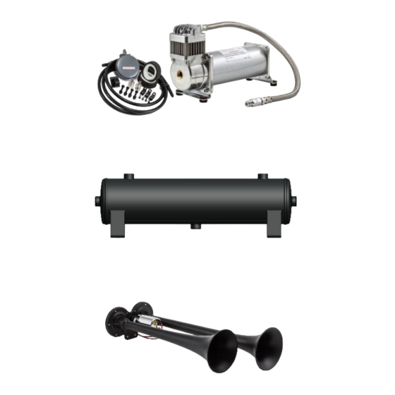
X3-KIT Installation and Operation Manual 7. Parts List 7.1. Before Starting, Review Parts List Unpackage and organize Kit across a large work area and verify all parts are included, as listed below. Contact Kleinn support if any questions arise. 7.1.1. Review pre-packaged Kit items (i.e., K1, K2, etc.) 7.1.2. -
Page 13: Air Fittings And Related Items
X3-KIT Installation and Operation Manual 7.3. Air Fittings and Related Items ITEM PART NUMBER DESCRIPTION PICTURE 2151 1/4" NPT PRESSURE SWITCH (view location on Air Tank) 54440 1/4" NPT "T" MANIFOLD, FEMALE (view location on Air Tank) 59014 1/4" NPT X 1/4" NPT FEMALE, 90 (view location on Air DEG. -
Page 14: Electrical Small Components And Related Items
X3-KIT Installation and Operation Manual 51414F 1/4" NPT X 1/4" TUBING FEMALE, STRAIGHT (USED ON COMPRESSOR LEADER HOSE END) 25014 1/4" AIR TUBING, 20 FT. LONG (USE 6 FT. FOR COMPRESSOR, 14 FT. FOR AIR HORN) KLEINN AIR HORN THREAD SEALENT FOR NPT... -
Page 15: Bolt-On Mounting Brackets & Special Hardware
X3-KIT Installation and Operation Manual 1" OD X 1FT. LONG 1” WIRE LOOM CORRUGATED AND SPLIT 321-W HORN ROCKER SWITCH, WITH BACKLIT HORN LOGO 7.5. Bolt-On Mounting Brackets & Special Hardware ITEM PART NUMBER DESCRIPTION PICTURE X3-101 COMPRESSOR BRACKET, OUTER... -
Page 16: Hardware, Fasteners And Soft Parts
X3-KIT Installation and Operation Manual X3-204 SPACER, BRACKET HALF, MACHINED X3-301 HORN BRACKET, CUT AND FORMED X3-302 HORN STABILIZER BRACKET, CUT AND FORMED 7.6. Hardware, Fasteners and Soft Parts NOTE: Pictures only indicative, not to scale and may not represent exact item ITEM QTY. - Page 17 X3-KIT Installation and Operation Manual 5/16"-18 X 1.00" SQUARE NECK BOLT, GRADE 2, LONG ZINC-PLATED 5/16"-18 X 2.50" SQUARE NECK BOLT, GRADE 2, LONG ZINC-PLATED 5/16" ID X 0.88" OD FLAT WASHER, USS, ZINC- PLATED 5/16" ID X 0.69" OD...
- Page 18 X3-KIT Installation and Operation Manual M5 X 0.8 X 10MM BUTTON HEAD CAP SCREW, LONG BLACK-OXIDE 1/4" ID X 0.63" OD FLAT WASHER, SAE, BLACK- OXIDE LOCK WASHER, SPLIT, BLACK- OXIDE 1 1/16" OD X 1/2" ID PRESS-IN RUBBER GROMMET X 3/8"...
-
Page 19: On-Vehicle Mechanical Assembly Steps
X3-KIT Installation and Operation Manual 8. On-Vehicle Mechanical Assembly Steps 8.1. Plan Location of Quick Connect Air Coupler 8.1.1. Before installing Brackets, review how kit installs and decide whether to install coupler to vehicle body, frame, or onto supplied brackets; this facilitates later routing Air Tubing and attaching Coupler. - Page 20 X3-KIT Installation and Operation Manual 8.2.4. Remove single T15 screw holding rear of fender near inside of brake light, as shown below. FRONT T15 Screw Figure 4 – Passenger Rear Fender Removal (below tail light) 8.2.5. Pull fender outwards from body and rest on tire to reduce stress on Brake Light Wiring, as shown below.
-
Page 21: Remove Driver Side Rear Fender
X3-KIT Installation and Operation Manual 8.3. Remove Driver side Rear Fender 8.3.1. Repeat previous steps for Passenger Fender removal. 8.4. Air Tank Brackets - Installation 8.4.1. Gather Brackets X3-201, X3-202, X3-203 and X3-204 (2) 8.4.2. On passenger side of vehicle, remove two (2) bolts holding rear deck; as shown below. Do not discard large bolt, as it will be re-used. - Page 22 X3-KIT Installation and Operation Manual 8.4.3. Install Air Tank Bracket (X3-202, 203 & 204) on chassis tube, using hardware #H5, H6, H8, H9 & H10, as shown below. Hand-tighten hardware only, so Bracket can still be rotated and moved along tube.
- Page 23 X3-KIT Installation and Operation Manual 8.4.4. Install Air Tank Bracket X3-201 onto Rear Deck support tubes, using hardware #H11, H12, H13, H15 & H16, as shown below. Hand-tighten hardware only, so Bracket can still be adjusted for Air Tank, as needed.
-
Page 24: Air Tank Fittings - Bench Assembly
X3-KIT Installation and Operation Manual 8.5. Air Tank Fittings - Bench Assembly 8.5.1. Gather all necessary Air Fittings and Air Tank; ensure all threads on fittings and inside ports are clean. 8.5.2. Apply two small drops of Kleinn Air Horn Juice to each male pipe thread. -
Page 25: Air Tank - Installation
X3-KIT Installation and Operation Manual 8.6. Air Tank - Installation 8.6.1. Before starting, ensure at least 6 FT. of supplied ¼” Air Tubing is connected to Air Tank front port, to allow easily routing across rear firewall/chassis and connecting to Air Compressor. -
Page 26: Air Compressor Bracket - Installation
X3-KIT Installation and Operation Manual 8.7. Air Compressor Bracket - Installation 8.7.1. Gather Brackets X3-101, X3-202 and X3-204 (2) 8.7.2. On Driver side of vehicle, remove one bolt holding rear deck; as shown below. M6 bolt and nut (i.e., front bolt) will be replaced and may be discarded. - Page 27 X3-KIT Installation and Operation Manual 8.7.3. Install Air Compressor Brackets (X3-101, 202 & 204) on chassis tube, using hardware #H5, H6, H8, H9, H10, H11, H12, H15 & H16 as shown below. Once Bracket is properly positioned, final torque all bolts.
-
Page 28: Air Compressor - Installation
X3-KIT Installation and Operation Manual 8.8. Air Compressor - Installation 8.8.1. Route 1/4” air tubing connected to front of Air Tank across back of firewall, or above chassis, as desired and secure using supplied zip ties. There should be 12 inches of excess tubing sticking out of Driver’s side to manipulate and connect to Air Compressor WARNING: Route plastic tubing distant from heat sources;... - Page 29 X3-KIT Installation and Operation Manual 8.8.3. Install Air Compressor on to X3-101 Bracket using hardware included inside Compressor packaging, as shown below. Final torque all bolts. Connect previously routed 1/4” Air Tubing to Leader Hose end. Connect to FRONT 1/4” Tubing...
-
Page 30: Air Horn - Installation
X3-KIT Installation and Operation Manual 8.9. Air Horn - Installation 8.9.1. Disassemble Trumpets from Air Horn Driver (item 3 in below picture), by grasping Trumpet throats with hand and twisting counter-clockwise; it may be necessary to clamp Air Horn Driver. Air Horn should be separated into three components, as shown below. - Page 31 X3-KIT Installation and Operation Manual 8.9.4. Remove three (3) M12 OE bolts that hold front sway bar and remove small T30 bolt holding Brake Line next to firewall, as shown below. Use care removing fasteners, as they will be re-used.
- Page 32 X3-KIT Installation and Operation Manual 8.9.7. Install X3-302 Trumpet Support Clamp and Insert Trumpets, using hardware H8, H9 & H10. Loosely tighten hardware, so X3-302 can still be positioned. Once hardware is installed, remove tape holding bottom side of carriage bolts to Bracket.
- Page 33 X3-KIT Installation and Operation Manual 8.9.8. On bench, connect remaining amount of supplied 1/4” Air Tubing to Air Fitting on Air Horn Solenoid, then install Air Horn Driver to Bracket using hardware H1, H1, H3 & H4. Loosely tighten hardware, as shown below.
-
Page 34: Connect Remote Quick Connect Kit To Vehicle
X3-KIT Installation and Operation Manual 8.9.10. Route Air Tubing back to Air Tank, as desired and safely secure to frame away from heat and sharp edges using zip-ties. Attach to proper port listed in figure 12 above. 8.9.11. Final installation of Air Horn should match below pictures. -
Page 35: On-Vehicle Electrical Installation
X3-KIT Installation and Operation Manual 9. On-Vehicle Electrical Installation CAUTION: Follow all recommended safety precautions for working on vehicle’s electrical system; consult vehicle owner’s manual for further instruction. 9.1. Relay and Fuse Diagram for Air Horn System Figure 33 – Suggested Ignition Relay Diagram for Air Horn System... -
Page 36: Review Suggested Wire Routing For Air Horn System
X3-KIT Installation and Operation Manual 9.2. Review suggested Wire Routing for Air Horn System Figure 34 – Suggested Wire Routing for Horn, Air Compressor, and Pressure Switch 9.3. Disconnect Vehicle Battery(s) 9.3.1. Remove Passenger side seat or move it forward to expose Battery. Consult Owner’s Manual. -
Page 37: Install Horn Button
X3-KIT Installation and Operation Manual 9.4.2. Insert all wiring into included wire loom and ensure loom is away from all sharp edges, hot vehicle parts (i.e., exhaust, engine, radiator), and fasten securely to vehicle using zip ties, or equivalent. NOTE: Do not cut wires to length until 100% sure of length required for final connections. -
Page 38: Initial Testing Of Kit
X3-KIT Installation and Operation Manual WARNING: NEVER operate train horns with ears 10. Initial Testing of Kit close to trumpets or in an enclosed space 10.1. Reconnect Vehicle Battery(s) without substantial hearing protection (i.e., > CAUTION: Before connecting vehicle battery(s),... -
Page 39: General Operation Of Kit
X3-KIT Installation and Operation Manual 12.1. Yearly, or every 12000 miles verify all 11. General Operation of Kit mounting fasteners are properly torqued; 11.1. Compressor Operation applying witness marks across fasteners and mounting parts is good practice to quickly WARNING: Never operate Air Compressor above ensure fasteners have not moved. -
Page 40: Warranty Information
Installation and Operation Manual 13. Warranty Information Thank you for purchasing this X3-KIT. Shall you experience any unexpected problems during installation or have problems with any part at any time please contact Kleinn support. © Kleinn Air Horns 2019, All rights reserved.
Need help?
Do you have a question about the X3-KIT and is the answer not in the manual?
Questions and answers