Dell Vostro 5480 Owner's Manual
Hide thumbs
Also See for Vostro 5480:
- Quick start manual ,
- Owner's manual (106 pages) ,
- Service manual (81 pages)

Subscribe to Our Youtube Channel
Related Manuals for Dell Vostro 5480


Summary of Contents for Dell Vostro 5480
- Page 1 Dell Vostro 5480 Owner's Manual Regulatory Model: P41G Regulatory Type: P41G002 November 2022 Rev. A03...
- Page 2 A WARNING indicates a potential for property damage, personal injury, or death. © 2012-2022 Dell Inc. or its subsidiaries. All rights reserved. Dell Technologies, Dell, and other trademarks are trademarks of Dell Inc. or its subsidiaries. Other trademarks may be trademarks of their respective owners.
-
Page 3: Table Of Contents
Contents Chapter 1: Working on your computer................... 5 Safety precautions................................5 Before working inside your computer..........................5 Turning Off Your Computer.............................. 6 After working inside your computer..........................7 Chapter 2: Disassembly and reassembly..................8 Recommended tools................................8 System Overview.................................9 Removing the Base Cover............................... 10 Installing the Base Cover.............................. - Page 4 Enhanced Pre-Boot System Assessment — ePSA diagnostics................34 Battery status light................................34 Device status lights................................35 LED Error Codes................................35 Chapter 5: Specifications......................36 Technical Specification..............................36 Chapter 6: Contacting Dell......................40 Contacting Dell.................................. 40 Contents...
-
Page 5: Chapter 1: Working On Your Computer
Standby power Dell products with standby power must be unplugged before you open the case. Systems that incorporate standby power are essentially powered while turned off. The internal power enables the system to be remotely turned on (wake on LAN) and suspended into a sleep mode and has other advanced power management features. -
Page 6: Turning Off Your Computer
CAUTION: To disconnect a network cable, first unplug the cable from your computer and then unplug the cable from the network device. 4. Disconnect all network cables from the computer. 5. Disconnect your computer and all attached devices from their electrical outlets. 6. -
Page 7: After Working Inside Your Computer
After you complete any replacement procedure, ensure that you connect external devices, cards, and cables before turning on your computer. CAUTION: To avoid damage to the computer, use only the battery designed for this particular Dell computer. Do not use batteries designed for other Dell computers. Steps 1. -
Page 8: Chapter 2: Disassembly And Reassembly
Disassembly and reassembly Topics: • Recommended tools • System Overview • Removing the Base Cover • Installing the Base Cover • Removing the Battery • Installing the Battery • Removing the Hard Disk Drive • Installing the Hard Drive • Removing the Coin-Cell Battery •... -
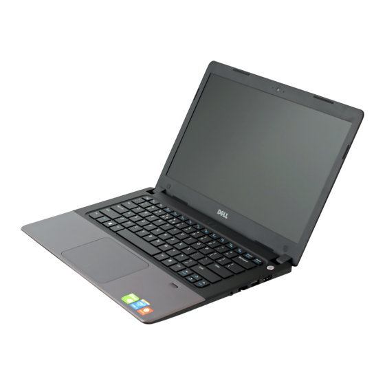
Page 9: System Overview
System Overview 1. camera-status light 2. camera 3. microphone 4. power-status light 5. battery-status light 6. hard-drive activity light 7. power button 8. HDMI connector 9. USB 3.0 connector 10. network connector 11. headset connector 12. fingerprint reader 13. microphones 14. -
Page 10: Removing The Base Cover
15. memory card reader 16. USB 3.0 connector 17. USB 3.0 connector with PowerShare 18. power connector 19. security-cable slot 20. service-tag label 21. sub-woofer speaker 22. speakers Removing the Base Cover Steps 1. Follow the procedures in Before Working Inside Your Computer. -
Page 11: Installing The Base Cover
4. Lift and remove the base cover from the computer. Installing the Base Cover Steps 1. Place the base cover to align with the screw holes on the computer. Disassembly and reassembly... -
Page 12: Removing The Battery
2. Tighten the screws to secure the base cover to the computer. 3. Follow the procedures in After Working Inside Your computer. Removing the Battery Steps 1. Follow the procedures in Before Working Inside Your Computer. 2. Remove the base cover. -
Page 13: Installing The Battery
5. Lift and remove the battery from the computer. Installing the Battery Steps 1. Place the battery into its slot on the computer. 2. Connect the battery cable to its connector on the system board. 3. Install the base cover. 4. -
Page 14: Removing The Hard Disk Drive
Removing the Hard Disk Drive Steps 1. Follow the procedures in Before Working Inside Your Computer. 2. Remove : base cover battery 3. Lift the hard drive assembly in an upward direction to release it from its compartment on the computer. Remove the hard drive from the computer. -
Page 15: Installing The Coin-Cell Battery
2. Remove : base cover battery 3. Perform the steps as shown in the illustration: a. Disconnect the coin-cell battery cable from its connector on the system board. b. Unroute the coin-cell battery cable from the routing channel. c. Lift and remove the coin-cell from the computer. Installing the Coin-Cell Battery Steps 1. -
Page 16: Installing The Wlan Card
Installing the WLAN Card Steps 1. Insert the WLAN card into its connector at a 45–degree angle. 2. Tighten the screw to secure the WLAN card to the computer. 3. Connect the antenna cables to their respective connectors marked on the WLAN card. 4. - Page 17 5. Disconnect the right system fan cable from its connector on the system board. Peel away the system board flex cable from the right system fan. 6. Remove the screws that secure the right system fan to the system board. Disassembly and reassembly...
-
Page 18: Installing The System Fan
7. Lift and remove the right system fan from the computer. Installing the System Fan Steps 1. Place the right system fan into its original position in the system board and affix the system board flex cable. 2. Tighten the screws that secure the right system fan to the system board. 3. -
Page 19: Removing The Heatsink
5. Tighten the screws that secure the left system fan to the system board. 6. Connect the left system fan cable to its connector on the system board. 7. Install : battery base cover 8. Follow the procedures in After Working Inside Your computer. -
Page 20: Installing The Heatsink
Installing the Heatsink Steps 1. Place the heatsink into its original position on the system board. 2. Tighten the screws to secure the heatsink to the system board. 3. Install: system fan battery base cover 4. Follow the procedures in After Working Inside Your computer Removing the Memory Module Steps... -
Page 21: Installing The Memory
Installing the Memory Steps 1. Insert the memory module into the memory socket. 2. Press the memory module down until it clicks into place. 3. Install: heatsink system fan battery base cover 4. Follow the procedures in After Working Inside Your computer. -
Page 22: Installing The System Board
5. Remove the system board from the computer. Installing the System Board Steps 1. Place the system board into its original position on the chassis. 2. Install the screws that secure the system board to the chassis. 3. Connect : a. -
Page 23: Removing The Display Assembly
b. touchpad cable c. keyboard cable d. display cable e. speaker cable 4. Install : memory heatsink system fan battery base cover 5. Follow the procedures in After Working Inside Your computer Removing the Display Assembly Steps 1. Follow the procedures in Before Working Inside Your Computer. -
Page 24: Installing The Display Assembly
5. Detach the base panel from the display assembly.. Installing the Display Assembly Steps 1. Align the base panel of the computer to the display hinges. Disassembly and reassembly... -
Page 25: Removing The Display Bezel
2. Install the screws that secure the display hinges to the base panel 3. Connect the LVDS cable and the camera cable to the connectors on the system board. 4. Install : battery base cover 5. Follow the procedures in After Working Inside Your computer Removing the Display Bezel Steps... - Page 26 5. Remove the screws that secure the display bezel. 6. Pry along the inner edges of the display bezel and remove it. Disassembly and reassembly...
-
Page 27: Installing The Display Bezel
Installing the Display Bezel Steps 1. Align the display bezel by pressing along the edges. 2. Install the screws that secure the display bezel. 3. Install the plastic caps that secure the display bezel screws on both sides of the display bezel. 4. -
Page 28: Installing The Display Panel
4. Lift and remove the display panel from the display assembly. Installing the Display Panel Steps 1. Align the display panel to the display assembly by pressing along the edges. 2. Install the screws that secure the display panel. 3. Install: battery Disassembly and reassembly... -
Page 29: Removing The Camera
base cover display assembly display bezel 4. Follow the procedures in After Working Inside Your computer. Removing the Camera Steps 1. Follow the procedures in Before Working Inside Your Computer. 2. Remove : base cover battery display assembly display bezel display 3. -
Page 30: Chapter 3: System Setup
Boot sequence enables you to bypass the System Setup–defined boot device order and boot directly to a specific device (for example: optical drive or hard drive). During the Power-on Self-Test (POST), when the Dell logo appears, you can: ● Access System Setup by pressing F2 key ●... -
Page 31: Updating The Bios In Windows
Steps 1. Restart the computer. 2. Go to Dell.com/support. ● Enter the Service Tag or Express Service Code and click Submit. ● Click Detect Product and follow the instructions on screen. 3. If you are unable to detect or find the Service Tag, click Choose from all products. - Page 32 Table 1. Main System Time Re-sets the time on the computer's internal clock. System Date Re-sets the date on the computer's internal calendar. BIOS Version Displays the BIOS revision. Product Name Displays the product name and the model number. Service Tag Displays the service tag of your computer.
- Page 33 Table 3. Security Set Asset Tag This field displays your system's asset tag. If the asset tag is not already set, this field can be used to enter it. Set Admin Password Allows you to change or delete the administrator password. Set System Password Allows you to change or delete the system password.
-
Page 34: Chapter 4: Troubleshooting
Troubleshooting The following section describes common troubleshooting steps that can be performed to resolve certain problems on your computer. Topics: • Enhanced Pre-Boot System Assessment — ePSA diagnostics • Battery status light • Device status lights • LED Error Codes Enhanced Pre-Boot System Assessment —... -
Page 35: Device Status Lights
Device status lights Table 6. Device status lights Turns on when you turn on the computer and blinks when the computer is in a power management mode. Turns on when the computer reads or writes data. Turns on steadily or blinks to indicate battery charge status. LED Error Codes Diagnostic LED codes are communicated via the Power Button LED. -
Page 36: Chapter 5: Specifications
Specifications Topics: • Technical Specification Technical Specification NOTE: Offerings may vary by region. For more information regarding the configuration of your computer, click Start (Start icon) > Help and Support, and then select the option to view information about your computer. NOTE: In Windows 8, navigate to Help and Support to view information about your computer. - Page 37 Table 11. Audio (continued) Feature Description Internal microphone supports Digital microphone x 2 Speakers Volume controls Program menus and keyboard shortcut keys Table 12. Video Feature Description Video type UMA/DIS Video Controller: Intel HD graphics 5x00 Discrete Nvidia N15S-GM Data bus 64–bit External display support HDMI...
- Page 38 Table 16. Display (continued) Feature Description Operating angle 135–degree Refresh rate 60Hz /40Hz Minimum Viewing angles: Horizontal 40(L)/40( R) Vertical 10(up)/30(down) Pixel pitch 0.2265 (H) x 0.2265 (V) mm Table 17. Keyboard Feature Description Number of keys Table 18. Touchpad Feature Description Active Area:...
- Page 39 Table 20. AC Adapter (continued) Feature Description Temperature range: 0 ℃ to 40 ℃ Operating 95 ℃ Non-Operating Table 21. Physical Feature Non-Touch Touch Height 18.30 mm (0.72 inch) 19.35 mm (0.76 inch) Width 337.60 mm (13.29 inches) 337.60 mm (13.29 inches) Depth 233.50 mm (9.19 inch) 233.50 mm (9.19 inch)
-
Page 40: Chapter 6: Contacting Dell
About this task Dell provides several online and telephone-based support and service options. Availability varies by country and product, and some services may not be available in your area. To contact Dell for sales, technical support, or customer service issues: Steps 1.
Need help?
Do you have a question about the Vostro 5480 and is the answer not in the manual?
Questions and answers