Table of Contents
Advertisement
Quick Links
Advertisement
Table of Contents

Related Manuals for Duco iAV


Summary of Contents for Duco iAV
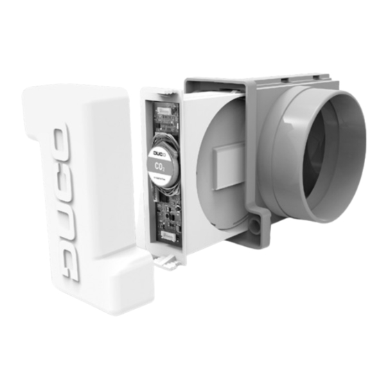
- Page 1 Control valve ENGLISH Quick Start L1020502 (Revision F | 25.10.2022)
-
Page 2: Table Of Contents
Translation of the original instructions (in Dutch) See www�duco�eu for information regarding warranty, maintenance, technical data, etc� Installation, connection, maintenance and repairs are to be carried out by an accredited installer� The electronic components of this product may be live� Avoid contact with water�... -
Page 3: Application
To control multiple iAV Control Valves simultaneously with one or more actuators (= zone with multiple valves), iAV Control Valves can be added as a wireless (RF) slave under a master iAV Control Valve� If an iAV is added as a slave , it can no longer be paired as a wired component with an IQ unit�... - Page 4 This configuration is especially suitable for utility projects with a pressure-controlled fan, where high flow rates per zone are required (e�g� classroom, open plan office���)� All iAV Control Valves are jointly opened or closed based on measurements in the iAV itself or from an external component such as a Room Sensor�...
- Page 5 All iAV Control Valves are jointly opened or closed based on measurements in the iAV itself or from an external component such as a Room Sensor�...
-
Page 6: Connections And Buttons
Transitional phase (please wait) the actuator, this may take a few minutes) WHITE or OFF Normal BLUE Visualisation of the Actuator board when changes are made via the master or Duco Network Tool L1020502 Quick start iAV control valve F | 25.10.2022) -
Page 7: Wiring
, the RF function of the IQ unit is disabled and no components can be installed directly below� Multiple iAV Control valves can be looped through (= recommended)� This means that a separate cable will not be required for each component�... -
Page 8: Mounting
DO NOT DISCONNECT THE CABLES YET! 1� To be able to remove the iAV Control valve from the casing, the valve must be in the closed position� Briefly press the INST button once to close the valve� The colour of the LED indicates the position of the valve, with bright white meaning 'open' and off mean- ing 'closed'�... -
Page 9: Installation
Activate Installer mode by tapping INST on the IQ unit� The LED will flash green rapidly� b� Tap the iAV Control valve 1x to pair it with the IQ unit so that the LED flashes green slowly� Tap again so the LED starts flash- ing quickly�... -
Page 10: 05�B Other Operations
Only perform steps 3e and 3f if additional control components are to be paired in the same zone� e� Press the INST button 1x of any slave iAV Control valve in this zone� For the operation it does not matter on which one, so the nearest one can be chosen�... -
Page 11: Air Calibration
See under the Tools heading at www�duco�eu for information about determining ventilation flow rates� The adjustment procedure depends on whether iAV is operated as master (stand alone) or as slave (external control)� 06.A Calibration with iAV as slave (EXTERNAL CONTROL) Follow the adjustment procedure described in the manual of the master unit�... - Page 12 ENGLISH Situation 2 : Multiple vents per iAV Control valve with equal flow rates Set all vents to the fully open position, regardless of the desired flow rate� Situation 3: Multiple vents per iAV Control valve with different flow rates Set the exhaust vents to match the desired flow rate in line with the table on page 11�...
- Page 13 (constant-volume controller), the point should be sought where the fan runs as low as possible while achieving the de- sired flow rate� If the fan speed cannot be adjusted, the desired flow rate can be achieved using the arrow keys on the iAV Control Valve from step 1�...
-
Page 14: Settings
This user-friendly software is the ideal way of changing settings and pinpointing problems in the system� The Duco Network Tool is issued to every installer after attending a free training course at the Duco Academy� Please refer to our website or your Duco dealer for further information�... -
Page 15: Maintenance
All warranty conditions concerning the DucoBox and DUCO's ventilation systems can be found on the DUCO website� All complaints are to be reported to DUCO by the DUCO distributor with a clear description and the order/invoice number under which the products were delivered� To do so, please fill out the complaint registration form, found on the DUCO website, mentioning the serial number and send it to service@duco�eu�... - Page 16 Installed by: L1020502 Document last modified on 25.10.2022 (revision F)
Need help?
Do you have a question about the iAV and is the answer not in the manual?
Questions and answers