Table of Contents
Advertisement
Quick Links
Advertisement
Table of Contents

Related Manuals for Balluff BDD-UM 3023


Summary of Contents for Balluff BDD-UM 3023
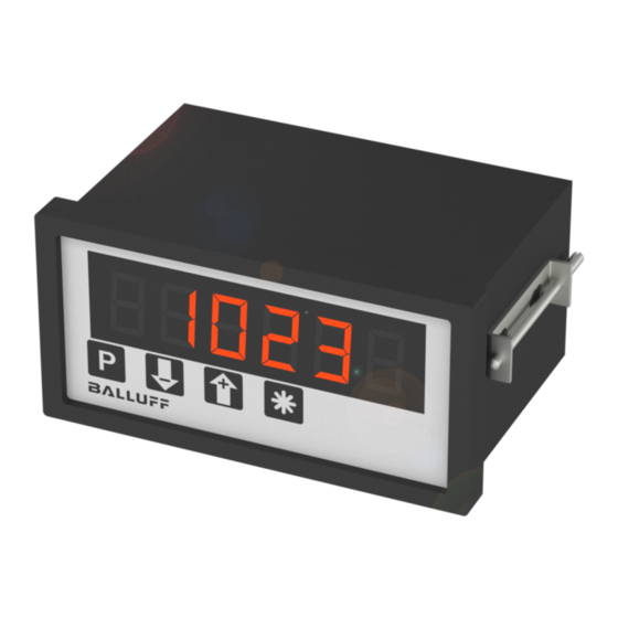
- Page 1 BDD-UM 3023 Digital Display for analogue input signals instruction manual alluff GmbH Schurwaldstrasse 9 73765 Neuhausen a.d.F. Germany Phone +49 (0) 71 58/1 73-0 Fax +49 (0) 71 58/50 10 Servicehotline +49 (0) 7158/1 73-3 70 E-Mail: balluff@balluff.de http://www.balluff.de...
- Page 2 Warranty For delivered products our " llgemeine Lieferungs- und Zahlungsbedingungen" are effective. In no event we or our suppliers shall be liable for any other damages whatsoever (including, without limitation, damages for loss of business profits, business interruption or other pecuniary loss) arising out of or inability to use this product. ll our products are warranted against defective material and workmanship for a period of two (2) years from date of delivery.
-
Page 3: Table Of Contents
Contents 1. Discription ......4 2. Security instructions ..... . 4 2.1. - Page 4 7.1.1. Scaling the display range ....12 7.2. Tare ......13 7.3.
-
Page 5: Discription
1. Discription Discription The digital panel meter model UM 3023 is an universal instrument for measuring analog input signals listed below: • Voltage 0 - 10 V • Current 0 - 20 mA / 4 - 20 mA Standard Hardware •... -
Page 6: Explanations Of Symbols
3. Mounting 2.1. Explanation of symbols Caution Attention Instruction Hint Caution: Dangerous! Attention: Will cause damage Instruction: If not noticed, trouble may occur. Hint: Useful hints for better operation. 3. Mounting 3.1. Place of operation Attention must be payed to the protection against humidity, dust and high temperatures at the place of operation. -
Page 7: Electrical Connections
4. Electrical connections 96,0 Panel cutout +0,8 92,0 15,0 55,5 Electrical connections 4.1. General Instructions • It is forbidden to plug or unplug connectors with voltage applied • Attach input and output wires to the connectors only without voltages applied •... -
Page 8: Hints Against Noisy Enviroment
4. Electrical connections 4.2. Hints against noisy enviroment All inputs and outputs are protected against noisy environment and high voltage spikes. Nevertheless the location should be selected to ensure that no capacitive or inductive interference can have an effect on the instrument or the connection lines. -
Page 9: Connection Of Input Signals
4. Electrical connections Pin assignment: Signal input current ground Signal input voltage Supply voltage (-) Signal ground Supply voltage (+) 4.4. Connection of input signals 4.4.1. Input voltage 0 - 10 V 1: 10 V 3: 0 V 4.4.2. Input current 0 - 20 mA, 4 - 20 mA 2: + 0/4 - 20 mA 4.5. -
Page 10: Start-Up
5. Start-Up 5. Start-Up Attention must be paid that the power supply voltage applied will agree with the voltage noticed at the type plate. Switch the power supply on (supply voltage applied to 5 (-) and 6 (+)). When delivered, the instrument is programmed with a standard configuration (default configuration). -
Page 11: Programming
7. Programming LED1 LED2 Description dark The displayed value is not tared lights The displayed value is tared yellow-orange green/flashes Programming mode is activated Programming The operation and the programming of the panel meter is organized in several programming levels. Programming is performed by the buttons on the front. Push button Function Selection of... -
Page 12: Programming Level For Configuration 0-00
7. Programming Selection of a parameter • select the parameter by pressing “+” -button oder “-” -button • Confirm the parameter by pressing the “P” -button. • The display shows the last programmed value of the selected parameter Change and confirm a selected parameter •... -
Page 13: Scaling The Display Range
7. Programming 7.1.1. Scaling the display range Over- and underflows are displayed as follows: An overflow is displayed as nnnn; this occurs if: • the input signal exceeds the permissible maximum around more than 0,5V or 1mA; e.g. input voltage >10,5 V or input current >21 mA. •... -
Page 14: Tare
7. Programming 7.2. Tare function The tare function works as follows: pushing the tare button will store the displayed value in the tare memory. The tare value will be substracted from the measured value. The tare value is stored in an non-volatile memory and will be saved even when the device is switched off. -
Page 15: Technical Specifications
8. Technical specifications Technical specifications Analog input Resolution : 10 Bit Input ranges voltage : 0 to 10 V, ± 0,1 %, ± 1 Digit impedance : > 50 kΩ current : 0/4 to 20 mA, ± 0,1 %, ± 1 Digit :10 Ω... -
Page 16: Notices
9. Notices 9. Notices... - Page 17 9. Notices...
- Page 18 9. Notices...
Need help?
Do you have a question about the BDD-UM 3023 and is the answer not in the manual?
Questions and answers