Table of Contents
Advertisement
Quick Links
Advertisement
Table of Contents

Related Manuals for Balluff BDD 750 P Series


Summary of Contents for Balluff BDD 750 P Series
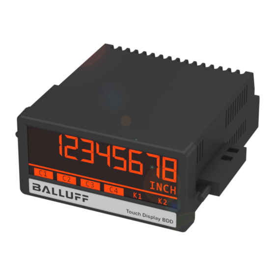
- Page 1 Touch Display BDD 750-_P… User’s Guide English...
- Page 2 All contents included in this manual are protected by the terms of use and copyrights of Balluff GmbH. Any reproduction, modification, usage or publication in other electronic and printed media as well as in the internet requires prior written authorization by Balluff GmbH.
-
Page 3: Table Of Contents
Table of content 1. Safety Instructions and Responsibility ........... 4 General Safety Instructions ..................4 1.1. Use according to the intended purpose ..............4 1.2. Installation ........................5 1.3. Cleaning, Maintenance and Service Notes ............5 1.4. 2. Introduction ..................... 6 Operation mode ...................... -
Page 4: Safety Instructions And Responsibility
1. Safety Instructions and Responsibility 1.1. General Safety Instructions This operation manual is a significant component of the unit and includes important rules and hints about the installation, function and usage. Non-observance can result in damage and/or impairment of the functions to the unit or the machine or even in injury to persons using the equipment! Please read the following instructions carefully before operating the device and observe all safety and warning instructions! Keep the manual for later use. -
Page 5: Installation
1.3. Installation The device is only allowed to be installed and operated within the permissible temperature range. Please ensure an adequate ventilation and avoid all direct contact between the device and hot or aggressive gases and liquids. Before installation or maintenance, the unit must be disconnected from all voltage-sources. Further it must be ensured that no danger can arise by touching the disconnected voltage-sources. -
Page 6: Introduction
2. Introduction The display device is designed for panel mounting. It is universally applicable, with its intuitive operation and the extensive features. 2.1. Operation mode All functions are can be configured in the parameter menu. The device can be set to one of the following operation modes: •... -
Page 7: Electrical Connections
3. Electrical Connections The terminal screws should be tightened with a slotted screwdriver (blade width 2mm). 3.1. DC Power Supply The unit accepts DC supply from 18 to 30 V at the terminals 1 and 2. The power consumption depends on the level of the supply voltage with approx. -
Page 8: Rs-485 Inputs And Outputs
3.3. RS-485 inputs and outputs At Terminal 5, 6, 7 and 8, the connection is available for the RS485 signals (Init + Sart-Stop impulse). Wiring for RS485 signals: DPI-Measurement mode: On the Init line, the Init impulse is sent to position encoder at regular intervals, whose rising flank triggers a measurement. -
Page 9: Control Inputs
3.4. Control Inputs The three control inputs at terminal 10, 11 and 12 have HTL PNP characteristics. In the COMMAND MENU the programmable functions for the control inputs can be assigned. Available functions are: display switching, locking the touch screen or release the lock function of the control or relay outputs. -
Page 10: Display And Touch Screen
4. Display and touch screen 4.1. Screen structure for parametrization The parameter menus and the parameters are described in chapter 5. Start setup procedure: To edit the parameters, press the touchscreen for 3 seconds. Menu selection: Select the parameter menu via arrow buttons and confirm with “OK”. -
Page 11: Screen Structure In Operation
4.2. Screen structure in operation The following displays are available during operation. Depending on the device version and the selected operating mode, only certain representations are displayed. Display with unit and status bar To switch to the next display, press the touch screen. Display with command keys To switch to the next display, press the top of the screen. -
Page 12: Error Message
4.3. Error Message ERROR: MAXIMUM DISPLAY VALUE Display value is greater than + 99,999,999 ERROR: MINIMUM DISPLAY VALUE Display value is less than-99,999,999 ERROR: POS. ENC. OUT OF RANGE No position encoder or position encoder outside the limits In case of error, the measurement result is set to 0. -
Page 13: Parameter / Overview-Menu Structure
5. Parameter / Overview-Menu Structure This section provides an overview of the menus and their parameters. The menu names are printed bold and the associated parameters are listed under the menu name. Depending on the device version and the selected operation mode, only the necessary menus / parameters are shown. Menu / Parameter Menu / Parameter GENERAL MENU... -
Page 14: General Menu
5.1. General Menu OPERATIONAL MODE This parameter determines which measurement function (mode) the device should run. Distance measurement DISTANCE Angle measurement (display in degrees) ANGLE LENGHT PER REVOLUTION ( in millimeters) This is the distance travelled (circumference) per 360 degrees and is indicated in "mm". 00000.100 Smallest value 01000.000... - Page 15 Continuation „General Menu“: SCALE UNITS This parameter defines the required engineering unit. This parameter does not affect the calculation of the display value. The number of decimal places must be defined with the parameter DECIMAL POINT, the corresponding scaling must be defined with the parameters FACTOR and DIVIDER. inch feet Default...
- Page 16 Continuation „General Menu“: AVERAGE FILTER (filter for average value) The average value can be switched to avoid display fluctuations. No average value Flowing mean value with 2 cycles Flowing average value with 4 cycles Flowing average value with 8 cycles Flowing mean value with 16 cycles LINEARIZATION MODE This parameter defines the linearization function.
-
Page 17: Encoder Properties
5.2. Encoder Properties SAMPLING TIME (S) Period duration between two init pulses (in milliseconds). Corresponds to the time after a new measurement is started and directly affects the reaction time of the device. 00.200 Minimum measurement time 04.000 Default value 16.000 Maximum measurement time VELOCITY (M/S) -
Page 18: Preselection Values
5.3. Preselection Values This menu is used to set the preselection values or the switching points. The preselection values / switching points are always referred to the display value. (Position value relative to the reference zero point or machine zero that was stored in the parameter offset.) PRESELECTION 1 Preselection / switching point 1 -99999999... -
Page 19: Preselection 1 Menu
5.4. Preselection 1 Menu MODE 1 Switching conditions for preselection 1. Output/ relay/ display switches under the following conditions: Absolute value of the display value is greater or equal absolute value of PRESELECTION 1 With HYSTERESIS 1 not equal 0 the following switching condition is 0 |RESULT|>=|PRES| applied: Display value >= PRESELECTION 1 ... - Page 20 Continuation „Preselection 1 Menu“: PULSE TIME 1 (S) Duration of output pulse for the switching condition of preselection 1 0,000 No output pulse (static signal) … 60,000 Pulse duration of 60 seconds OUTPUT TARGET 1 Assignment of an output or relay for the switching condition of preselection 1. If more than one switching condition is assigned to one output / relay, the output is set when at least one switching condition is true No assignment...
-
Page 21: Preselection 2 Menu
5.5. Preselection 2 Menu MODE 2 Switching conditions for preselection 2., see chapter PRESELECTION 1 MENU (except the trailing value) see chapter PRESELECTION 1 MENU Trailing preselection 2: Display value is greater or equal to PRESELECTION 1 – PRESELECTION 2 RES>=PRES- ON, TRAIL... -
Page 22: Preselection 3 Menu
5.6. Preselection 3 Menu MODE 3 Switching conditions for preselection 3., see chapter PRESELECTION 1 MENU (except the trailing value) See chapter PRESELECTION 1 MENU Trailing preselection 3: Display value is greater or equal to PRESELECTION 4 – PRESELECTION 3 RES>=PRES- TRAIL PRESELECTION 3 is the trailing preselection from PRESELECTION 4. -
Page 23: Preselection 4 Menu
5.7. Preselection 4 Menu MODE 4 Switching conditions for preselection 4., see chapter PRESELECTION 1 MENU (except the trailing value) See chapter PRESELECTION 1 MENU Trailing preselection 4: Display value is greater or equal to PRESELECTION 3 – PRESELECTION 4 RES>=PRES- TRAIL PRESELECTION 4 is the trailing preselection from PRESELECTION 3. -
Page 24: Command Menu
Command Menu 5.8. INPUT 1 ACTION (function Input 1) This parameter defines the function of the input “Ctrl. In 1”. No function Power fail-safe stored transfer of the current position to the (d) (s) RESET/SET VALUE parameter "offset". Example Application: non-volatile setting of the machine zero point. - Page 25 Continuation „Command Menu“: INPUT 1 CONFIG This parameter defines the switching characteristics of the input “Ctrl. In 1”. Active at „LOW“ (static) ACTIVE LOW Active at „HIGH“ (static) ACTIVE HIGH RISING EDGE Activate at rising edge FALLING EDGE Activate at falling edge INPUT 2 ACTION This parameter defines the function of the input “Ctrl.
-
Page 26: Display Menu
5.9. Display Menu COLOR This parameter defines the display color. Event-depending change of the display color by a switching condition is possible (see PRESELECTION 1…4 MENU) Red display GREEN Green display YELLOW Yellow display BRIGHTNESS (%) This parameter defines the brightness of the display in percent Min. -
Page 27: Linearization Menu
5.10. Linearization Menu The linearization function is defined in this menu. This menu will only be showed, if the LINEARIZATION MODE in GENERAL MENU is selected. Linearization description and examples are shown in the appendix. P1(X) … P24(X) X-coordinate of the linearization point. This value representing the display value which the unit show in the display without linearization. -
Page 28: Appendix
6. Appendix 6.1. Parameter / serial codes Menu Name Serial Code Default OPERATIONAL GENERAL MENU MODE LENGHT PER REV. GENERAL MENU 99999999 1000000 (MM) GENERAL MENU FACTOR -99999999 99999999 GENERAL MENU DIVIDER -99999999 99999999 GENERAL MENU ADDITIVE VALUE -99999999 99999999 GENERAL MENU DECIMAL POINT GENERAL MENU... - Page 29 Continuation „Parameter / serial codes”: Menu Name Serial Code Default PRESELECTION 2 MODE 2 MENU PRESELECTION 2 HYSTERESIS 2 99999999 MENU PRESELECTION 2 PULSE TIME 2 (S) 60000 MENU PRESELECTION 2 OUTPUT TARGET 2 MENU PRESELECTION 2 OUTPUT POLARITY MENU PRESELECTION 2 OUTPUT LOCK 2 MENU...
- Page 30 Continuation „Parameter / serial codes”: Menu Name Serial Code Default COMMAND MENU INPUT 1 ACTION COMMAND MENU INPUT 1 CONFIG. COMMAND MENU INPUT 2 ACTION COMMAND MENU INPUT 2 CONFIG. COMMAND MENU INPUT 3 ACTION COMMAND MENU INPUT 3 CONFIG. COMMAND MENU COMMAND MENU COMMAND MENU...
- Page 31 Continuation „Parameter / serial codes”: Menu Name Serial Code Default LINEARIZATION MENU P15(X) -99999999 99999999 LINEARIZATION MENU P15(Y) -99999999 99999999 LINEARIZATION MENU P16(X) -99999999 99999999 LINEARIZATION MENU P16(Y) -99999999 99999999 LINEARIZATION MENU P17(X) -99999999 99999999 LINEARIZATION MENU P17(Y) -99999999 99999999 LINEARIZATION MENU P18(X) -99999999...
-
Page 32: Linearization
6.2. Linearization The linearization function of this unit allows converting a linear input signal into a non-linear developing (or vice versa). There are 24 programmable x/y coordinates available, which can be set in any desired distance over the full conversion range. Between two coordinates, the unit uses linear interpolation. Therefore it is advisable to use more coordinates in a range with strong curves and only a few coordinates where the curvature is less. - Page 33 Application Example: The picture below shows a watergate where the opening is picked up by means of an incremental encoder. We would like to display the clearance of the gate "d", but the existing encoder information is proportional to the angular information φ.
-
Page 34: Dimensions
6.3. Dimensions... -
Page 35: Technical Specifications
6.4. Technical Specifications: Technical Specifications: Connections: Connector type: screw terminal, 1.5 mm² / AWG 16 18 … 30 VDC Power supply (DC): Input voltage: Protection circuit: reverse polarity protection Consumption: approx. 100 mA (unloaded) Fuse protection: extern: T 0.5 A Encoder supply: DC version: 24 VDC (approx. - Page 36 US Service Center CN Service Center Germany Germany China Balluff GmbH Balluff GmbH Balluff Inc. Balluff (Shanghai) trading Co., ltd. Schurwaldstrasse 9 Schurwaldstrasse 9 8125 Holton Drive Room 1006, Pujian Rd. 145. 73765 Neuhausen a.d.F. 73765 Neuhausen a.d.F. Florence, KY 41042 Shanghai, 200127, P.R.
Need help?
Do you have a question about the BDD 750 P Series and is the answer not in the manual?
Questions and answers