Gotting HG G-73650ZD Basics, Setup And Software
Navigation controller
Hide thumbs
Also See for HG G-73650ZD:
- Basics, setup and software (206 pages) ,
- Basics, setup and software (158 pages)
Table of Contents
Advertisement
Quick Links
Documentation
Navigation Controller
English, Revision 04
Date: 28.10.2016
Götting KG, Celler Str. 5, D-31275 Lehrte - Röddensen (Germany), Tel.: +49 (0) 51 36 / 80 96 -0,
Fax: +49 (0) 51 36 / 80 96 -80, eMail: techdoc@goetting.de, Internet: www.goetting.de
Basics, Setup and Software
HG G-73650ZD
Dev. by:
ML / LM
Author(s):
RAD / AF / Ext.
HG G-73650ZD
Advertisement
Chapters
Table of Contents

Related Manuals for Gotting HG G-73650ZD


Summary of Contents for Gotting HG G-73650ZD
- Page 1 Documentation HG G-73650ZD Navigation Controller Basics, Setup and Software HG G-73650ZD English, Revision 04 Dev. by: ML / LM Date: 28.10.2016...
-
Page 2: Table Of Contents
Contents HG G-73650ZD Contents Introduction ...............7 Tasks of the Navigation Controller........... 7 Intended Use ................7 Requirements / Options ............8 Basic Principles of Track Guidance ........9 Suitable and Unsuitable Vehicle Types ........9 System Composition ............. 10 Position Determination with Sensor Fusion ......10 2.3.1... - Page 3 Contents HG G-73650ZD 2.6.4 Guidance of a non-omnidirectional Vehicle ........34 2.6.5 Driving Modes ................35 2.6.5.1 Idle Mode ................35 2.6.5.2 Parameter Test Mode ............. 35 2.6.5.3 Automatic Mode ..............35 2.6.5.4 Remote Control Mode ............. 36 2.6.5.5 Vector Steering Mode ............. 36 Communication with the Vehicle Control (e.g.
- Page 4 Contents HG G-73650ZD 4.2.3.1 GPS ..................54 4.2.3.2 ONS ..................54 4.2.3.3 Controller Deviation ..............55 4.2.3.4 Controller Correction ............... 55 4.2.3.5 Status ..................55 4.2.4 GPS Receiver................56 4.2.4.1 UTC..................56 4.2.4.2 Status ..................56 4.2.4.3 Position .................. 56 4.2.4.4...
- Page 5 Contents HG G-73650ZD Segment Table menu ............84 Transponder File menu ............85 4.8.1 Upload Transponder File —> Transfer a transponder file from the PC into the navigation controller ............85 4.8.2 Download Segment File —> Transfer transponder file from the naviga- tion controller into a file on the PC ..........
- Page 6 Contents HG G-73650ZD Transmission Telegrams from Control Unit to PLC, the Wheels and the Gyro ...............109 6.1.1 Path Data Box ................109 6.1.2 Segment Search Box ..............110 6.1.3 Status Box................. 111 6.1.4 Error Box ................... 112 6.1.5 Wheel Boxes ................116 6.1.6...
- Page 7 Contents HG G-73650ZD 15.3 Trade Marks and Company Names........164 English, Revision 04, Date: 28.10.2016...
-
Page 8: Introduction
Introduction HG G-73650ZD Introduction The subject of this manual is the Navigation Controller HG G-73650ZD that enables AGV (Automated Guided Vehicles) to follow virtual tracks. The following terms are used synonymously throughout this document: Control Unit (as printed onto the hardware) -
Page 9: Requirements / Options
Introduction HG G-73650ZD wheels have to be entered with utmost accuracy. Consequently for new projects a comprehensive testing of the settings with a jacked-up vehicle within a closed down section of the plant is always recommended. ATTENTION! As vehicles using the steering controller usually drive fully auto-... -
Page 10: Basic Principles Of Track Guidance
Basic Principles of Track Guidance HG G-73650ZD Basic Principles of Track Guidance 2.1 Suitable and Unsuitable Vehicle Types The range of particularly suitable vehicle types covers all vehicles that operate pre- dictably and reproducibly. Several non-steered axles, trailers or vehicles with a center pivot steering are not suitable.The wheel slippage has to be low and the wheels should... -
Page 11: System Composition
Basic Principles of Track Guidance HG G-73650ZD 2.2 System Composition Narrow-band Narrow-band Central RF Modem RF Modem Control (optional) (optional) Unit GPS Antennas 1 & 2 (optional) Navigation Controller IO 4 Incremental Emergency Stop Encoder (optional) (optional) Incremental Break (optional) -
Page 12: The Odometry
Basic Principles of Track Guidance HG G-73650ZD If the internal sensor fusion is used, the position of the vehicle is calculated from the odometry, initialized and corrected by the transponder antenna and/or the GPS sys- tem. The transponder antennas will then be connected via CAN bus. Additionally their posi pulse has to be connected with IO-3 (see manual of the antenna). -
Page 13: Figure 4 Determination Of Antenna Positions Underneath The Vehicle
Basic Principles of Track Guidance HG G-73650ZD size). Also depending on the antenna type the detection range is between ±125 and up to ± 500mm, the reading distance varies between 50 - 200 mm. Possible antennas are e.g. the Götting types HG 98810, HG 98820 and HG 98850. -
Page 14: Single Antenna Evaluation - Calculation Of The Position With One Antenna
Basic Principles of Track Guidance HG G-73650ZD 2.3.2.1.1 Single Antenna Evaluation — Calculation of the Position with one Antenna Vehicle Y Antenna 3 Front Vehicle X Single antenna: Placement Figure 5 In order to be able to calculate a position it is normally necessary... -
Page 15: Figure 6 Properties Of A Single Antenna Set-Up
Basic Principles of Track Guidance HG G-73650ZD Example 78,84 244,85 1500 Properties of a single antenna set-up Figure 6 Antenna properties: The orange area of the antenna represents the range where max. one transponder may be located. This area lies within a distance of approx. 50 mm around the antenna casing. -
Page 16: Double Antenna Evaluation
Basic Principles of Track Guidance HG G-73650ZD It should not be attempted to read transponders in tight turns. It is better to place a pair of transponders with a distance of at least 0.5 m before and after the curve. -
Page 17: The Triple Antenna Evaluation
Basic Principles of Track Guidance HG G-73650ZD 2.3.2.1.3 The Triple Antenna Evaluation Front Vehicle Y Antenna 1 Antenna 3 Antenna 2 Vehicle X Properties of a triple antenna set-up Figure 8 In contrast to the single and double antenna set-up in this application all degrees of freedom of the vehicle are measured directly. -
Page 18: The Transponder List
Basic Principles of Track Guidance HG G-73650ZD If the vehicle is also controlled by a driver (manual mode) it sometimes happens that the transponders are not crossed directly anymore. This results in an increasing dete- rioration of odometry accuracy. Since the system normally is not switched- off the only remaining possibility for initialization for a single antenna system then is the second alternative. -
Page 19: Coordinate Systems
Basic Principles of Track Guidance HG G-73650ZD 2.4 Coordinate Systems Within the Control Unit different coordinate systems are in use. Segments and tran- sponders refer to the local coordinate system (e.g. the coordinate system of the area). All components of the vehicle refer to the vehicle coordinate system. -
Page 20: Characteristics Of The Coordinate Systems
Basic Principles of Track Guidance HG G-73650ZD When the GPS system is used either a local base station (origin) or the country coordinate system are used. If no local base station is used the necessary GPS correction data (wireless) have to be leased from a local provider. -
Page 21: Reconstruction Of The Route (Segments)
Basic Principles of Track Guidance HG G-73650ZD Distances are slightly distorted. When using a local GPS base station a flat coordinate system is projected tangentially in north heading onto the ellipsoid. The base station then marks the origin. This still re- sults in projection errors. -
Page 22: The Segment File
Basic Principles of Track Guidance HG G-73650ZD The closer the support points lie to one another the more precisely the tracking will cor- relate with the virtual track. However, very close distances between the points are un- necessary where large vehicles are concerned because the vehicle cannot be driven that accurately. - Page 23 Basic Principles of Track Guidance HG G-73650ZD Seg- Point Speed Speed Attribute 32 Attribute ment X Pos. Y Pos. Heading Next 16 Bit 10000 0x00000002 9000 10000 0x00000001 9000 10000 0x00000000 9000 10000 1000 0x00000000 9000 10000 1500 0x00000000 9000...
-
Page 24: The Segment Search
Basic Principles of Track Guidance HG G-73650ZD Example for congruent segments Figure 13 Vehicle The vehicle always moves continuously through the segment in the direction of the support points (from the start of a segment to Segment 1 Segment 4 its end). -
Page 25: Figure 14 Segment Fifo Shifting Register
Basic Principles of Track Guidance HG G-73650ZD Completed Segment segments Register Support Point Segment Support Point Segment Support Point Segment Support Point Segment Segment Segment FIFO Track shifting register Segment Segment Segment Segment Segment Segment Segments to be driven Segment... -
Page 26: Transmission Of Segmente
Basic Principles of Track Guidance HG G-73650ZD Before After FIFO Segment FIFO Segment 65535 Segment No. 55 added 65535 65535 65535 65535 65535 65535 65535 65535 Example: Adding new segments to the FIFO Table 4 This way more than 8 segments can be traveled in a row. In order for the segments to be concatenated the end position of a segment must be the start position of the next segment. -
Page 27: Attributes
Basic Principles of Track Guidance HG G-73650ZD The navigation controller's CAN Box answer has a similar structure. This box indicates the current status of the segments in the navigation controller. The transmission of seg- ments in the Feldbus telegram is less complicated, here always 8 segments are trans- mitted together. -
Page 28: Inverted Steering
Basic Principles of Track Guidance HG G-73650ZD attribute is switched off while the vehicle still drives with offset, the vehicle stops with an error message. Therefore a free attribute should mark the end of the offset mode early enough before the vehicle is supposed to switch back to the track. -
Page 29: Stop Distance
Basic Principles of Track Guidance HG G-73650ZD In this example it is possible to tell the control unit to not attempt to steer right but to steer the wheel left with the attribute „Steer inverse“. Then enough steering angle is available to drive the curve. -
Page 30: Spot Turn
Basic Principles of Track Guidance HG G-73650ZD 2.5.3.4 Spot Turn The spot turn is a special maneuver that enables to turn the vehicle on a point. It is needed to change the direction of the vehicle with minimum need for space. Spot tunr can be enabled via the corresponding attribute for the first support point of a segment. -
Page 31: Track Guidance
Basic Principles of Track Guidance HG G-73650ZD Online Track Editor by Götting Figure 19 2.6 Track Guidance The navigation controller includes the track controller. The track controller calculates from the current position given by the sensor fusion (see section 2.3 on page 10) how to guide the vehicle to follow the intended track, which is defined by the different seg- ments and their support points (s. -
Page 32: Figure 20 Example Course With A Driving Job Consisting Of A Combination Of Segments
Basic Principles of Track Guidance HG G-73650ZD Segment 6 Segment 4 Segment 8 Segment 5 Segment 3 Segment 7 Segment 2 Driving job: Segments 1, 2, 3, 7 Segment 1 Vehicle Example course with a driving job consisting of a combination of segments Figure 20 The purpose of the navigation controller is to guide the vehicle on the intended track. -
Page 33: Speed Calculation
Basic Principles of Track Guidance HG G-73650ZD 2.6.1 Speed Calculation The speed is obtained from the information of the segment's support points. Here the velocity of the support point just passed and the upcoming support point is interpolat- ed. Which of the two support point velocities ("speed endpoint" or "speed connection") is selected depends on whether the vehicle shall stop at the segment's end or not. -
Page 34: Figure 22 Guiding An Omnidirectional Vehicle: Control Process
Basic Principles of Track Guidance HG G-73650ZD for the vehicle control. Here the vectors "Forward Dis.Fix" and "Forward Dis Var" will be added in the segment's direction of travel. "ForwardDis Var" results from the multiplica- tion of the corresponding parameter and the actual velocity in m/s. All steering angles of the vehicle are then calculated in such a way that the points "Virtual Point Front"... -
Page 35: Guidance Of A Non-Omnidirectional Vehicle
Basic Principles of Track Guidance HG G-73650ZD 2.6.4 Guidance of a non-omnidirectional Vehicle A non-omnidirectional vehicle has the fundamental disadvantage that it is unable to drive sideways to the segment. This is why the vehicle has to be steered towards the segment's direction at first to minimize deviations. -
Page 36: Driving Modes
Basic Principles of Track Guidance HG G-73650ZD When the vehicle travels backwards, it is mirrored at the fixed axle. Figure 24 above shows the real vehicle plotted with thick lines and the mirror-image with thin lines. In this case the vehicle control is depending on the point "Virtual Point Rear". If this point is controlled the fixed axle follows and the control is stable again. -
Page 37: Remote Control Mode
Basic Principles of Track Guidance HG G-73650ZD 2.6.5.4 Remote Control Mode In this mode the vehicle can be remote-controlled via the navigation controller. The only pre-settings here are the steering angle and the speed. Then the navigation con- troller calculates the speeds and steering angles of the individual wheels. -
Page 38: Communication With The Vehicle Control (E.g. Plc)
Basic Principles of Track Guidance HG G-73650ZD 2.7 Communication with the Vehicle Control (e.g. PLC) The navigation controller communicates with the vehicle PLC via CAN Bus or Feldbus. The vehicle PLC adapts the navigation controller to the vehicle. This offers the advan- tage of a standard interface. -
Page 39: Hardware
Hardware HG G-73650ZD Hardware The device described on the following pages is the hardware component of the Con- trol Unit, called HG G-61430ZD. Since the same hardware is used for the GPS system for RTG‘s the navigation controller as a whole has a type number based on its soft- ware, 73650. -
Page 40: Mounting
Hardware HG G-73650ZD 3.1 Mounting Dimensions of the control unit Hardware HG G-61430ZD Figure 26 The device is designed to be mounted on a 35 mm top hat rail according to EN50022. The mounting place has to be protected against humidity. Often a control cabinet is available for other components of the vehicle control. -
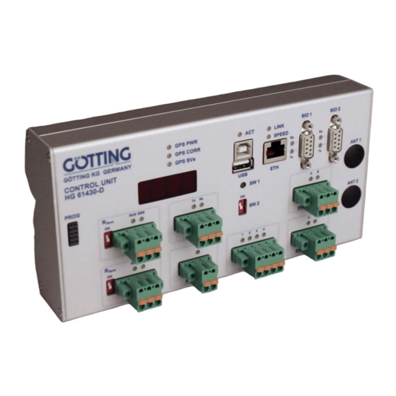
Page 41: Front Panel
Hardware HG G-73650ZD 3.2 Front Panel LED‘s and connectors Figure 27 3.3 Control Elements on Front Panel Element Position Meaning SW 1 Press button > 1 s Stop data recording and eject the USB stick. As soon as the LED ACT stops blinking the stick may be safely detached. -
Page 42: Connectors
Hardware HG G-73650ZD Meaning when LED is lit/flashing GPS SVs Reception of GNSS satellites SIO 1/Rx SIO 1 receiving data SIO 1/Tx SIO 1 transmitting data SIO 2/Rx SIO 2 receiving data SIO 2/Tx SIO 2 transmitting data SIO 3/Tx... -
Page 43: Sio 1 (Gps Receiver)
Hardware HG G-73650ZD 3.5.3 SIO 1 (GPS Receiver) Sketch of connector SIO 1 Figure 30 Function: Communication with internal GPS receiver (optional) Interface: RS 232 + Spannungsversorgung für externes Funkmodem Plug type: Sub-D 9 pins (DE9) female Function Direction +Ub (12-24 V) -
Page 44: Can 1
Hardware HG G-73650ZD 3.5.5 CAN 1 Sketch of connector CAN 1 Figure 32 Function: CAN Bus 1 Interface: CAN Spec. V2.0 part B Plug type: Phoenix-Contact FKCT 2,5/3-STF-5,08 Function Direction CAN High CAN Low Pin assignment SIO 2 Table 9 3.5.6... -
Page 45: Power
Hardware HG G-73650ZD 3.5.8 POWER Sketch of connector POWER Figure 35 Function: Energieversorgung 12 — 24 V Plug type: Phoenix-Contact FKCT 2,5/2-STF-5,08 Function Direction +Ub (12 — 24 V) Pin assignment SIO 2 Table 12 3.5.9 Sketch of connector IO... -
Page 46: Prog
Hardware HG G-73650ZD 3.5.11 PROG ATTENTION! Goetting internal use only! Do not connect! Sketch of connector PROG Figure 38 3.5.12 ANT1 / ANT2 Without option GPS: dummy plug With option GPS: 2 X TNC plugs for the connection of GPS antennas (s. Figure 25 on page 38) 3.6 Extension module Feldbus... -
Page 47: Software
Software HG G-73650ZD Software An HTTP server runs in the navigation controller and it can be addressed from outside. You can use an internet browser on the PC to do so. A browser that is as up to date as possible should be used, for example Google®... -
Page 48: Main Menu
Software HG G-73650ZD 4.1 Main menu IP address of the navigation controller (example) Display of the device type Display of the serial number and the firmware version Selection menu with sub-items for further configuration Screenshot: Main menu Figure 40 Several fundamental items of information regarding the device are displayed in the main menu. -
Page 49: Status Menu
Software HG G-73650ZD Parameter Test: Test mode for parameters and interfaces, for example during commissioning or troubleshooting. More information in the section entitled 'Tran- sponder Table': Display of the transponders stored in the navigation controller. More information in section 4.10 on page 87. -
Page 50: Deviation
Software HG G-73650ZD Pos Y: Y component of the position in the global co-ordinate system. Speed 1: Speed of wheel 1 Speed 2: Speed of wheel 2 Speed 3: Speed of wheel 3 Speed 4: Speed of wheel 4 Angle 1: Steering angle of wheel 1... -
Page 51: Segment
Software HG G-73650ZD NOTE! If the protocol is not complied with on transferring with the CAN bus, the new segment list does not appear and the old one remains. Seg 1-8: segments 4.2.1.4 Segment This table shows information on the segment currently being driven Actual Seg 1. The display is only current during automatic mode. -
Page 52: Plc
Software HG G-73650ZD 4.2.1.5 This table shows the data transferred from and to the vehicle control system. The table has three columns: PLC: Shows which value is involved. Value: Output of the value Unit: Unit of the value The following values are output: Mode: Mode in which the navigation controller is currently operating. -
Page 53: Antenna
Software HG G-73650ZD NOTE! Sensor fusion with transponders is only executed if it has been enabled in the parameters. Otherwise, this page is only dis- played and no values are updated. 4.2.2.1 Antenna This table shows the data of the antennas. The table has three columns: Antenna: Shows which value is involved. -
Page 54: Odometry
Software HG G-73650ZD Result: Shows which value is involved. Value: Output of the value Unit: Unit of the value The following values are displayed: Heading: Calculated alignment of the vehicle in the global co-ordinate system. X Pos: Calculated X position of the vehicle in the global co-ordinate system. -
Page 55: Gps
Software HG G-73650ZD This menu only has a function if GPS hardware is installed. 4.2.3.1 The table has three columns: 1. column: Shows which value is involved. 2nd column: Output of the value 3. column: Unit of the value The following values are displayed: Pos X... -
Page 56: Controller Deviation
Software HG G-73650ZD 4.2.3.3 Controller Deviation The table has three columns: 1. column: Shows which value is involved. 2nd column: Output of the value 3. column: Unit of the value The following values are displayed: Deviation Heading Deviation between GPS and ONS regarding the Heading (vehicle orientation) Deviation Pos X... -
Page 57: Gps Receiver
Software HG G-73650ZD Controller State State of the controller The GPS controller is started if the status is 0. The possible reasons that the controller is not running are binary coded: 0x01 Speed of the vehicle too slow 0x02 Log is high and control deviation of the angle controller too great... -
Page 58: Diff. Data Age
Software HG G-73650ZD 1st column: Shows which value is involved. 2nd column: Output of the value The following values are displayed: Latitude Geographical width (reference system WGS 84) Longitude Geographical length (reference system WGS 84) 4.2.4.4 Diff. Data Age Age of the correction data 4.2.4.5... -
Page 59: Error
Software HG G-73650ZD State State of the angle calculation Tilt Inclination Shift Tilt Shift of the position due to the inclination 4.2.5 Error Screenshot: Status —> Error Figure 45 Error messages are shown on this page. The Error table shows an overview of the cur- rent pending error messages. -
Page 60: Tcp
Software HG G-73650ZD 4.2.6 Screenshot: Status —> TCP Figure 46 The table has six columns: Socket: Serial number of the connection State: State of the connection (FREE, CLOSED, LISTEN, CONNECT) Rem IP: IP address of the remote device (PC) Rem Port: Port number of the remote device (PC) -
Page 61: Configuration -> Main
Software HG G-73650ZD If both requirements are met, the two buttons OK and Cancel appear. Subsequently, parameters can be changed and adopted with the OK button. If the changed values are not to be adopted, the Cancel button aborts the operation and restores the original values. - Page 62 Software HG G-73650ZD CAN2 Baudrate: Baud rate of the CAN bus 2. Normally, 250 or 500 kBit/s is used. Fusion transmit via CAN: Specifies whether the position calculated by the internal sensor fusion is sent via CAN bus. NOTE! If an external sensor fusion is used, sending the position must be disabled! Log Seg End: On some vehicles, the brakes take effect relatively slowly.
-
Page 63: Configuration -> Guidance
Software HG G-73650ZD 4.3.2 Configuration —> Guidance Screenshot: Configuration —> Guidance Figure 48 The CAN bus identifiers for communication with the vehicle control system are set in this menu. For the content of the messages, refer to the CAN bus description in chap- ter 6 on page 108. -
Page 64: Wheels
Software HG G-73650ZD 4.3.3 Wheels The parameters for the geometry of the vehicle are set in this menu. Before you set the first values, you have to consider the following fundamental settings: 4.3.3.1 What type of vehicle is involved? If the vehicle has an axle that cannot be steered independently, it is not an omnidi- rectional vehicle. -
Page 65: The Omnidirectional Vehicle
Software HG G-73650ZD 4.3.3.3 The omnidirectional vehicle Example: Vehicle Y Front Vehicle X Example: Omnidirectional vehicle Figure 51 On these vehicle, the vehicle zero point can be selected without restriction. If an axle only has a very small steering angle, it is advisable to set the vehicle zero point near to this axle, as otherwise only very large steering radii can be driven. -
Page 66: Configuration -> Wheels
Software HG G-73650ZD 4.3.3.6 Configuration —> Wheels Screenshot: Configuration —> Wheels Figure 53 Setting the vehicle geometry. The table has six columns: Item: Shows which value is involved. Wheel 1 to 4: Input of the values Unit: Unit of the value The following values can be changed: Type: The type of wheel can be specified here. - Page 67 Software HG G-73650ZD Contelec 2, absolute angle sensor made by Contelec, address 418 (0x1A2), node number 22 Contelec 2 Inv., for the event that the sensor is on its head, i.e. is inverted Servo if the steering angle is to be read from the steering servo Servo Inv., inverted value if the sensor rotates the other way around...
-
Page 68: Configuration -> Antennas
Software HG G-73650ZD Tolerance Angle: Tolerance of monitoring the steering angle of the corresponding wheel Tolerance Speed: Tolerance of monitoring the speed of the corresponding wheel CAN Tx: CAN identifier of the messages of the corresponding wheel sent by the navigation controller (see CAN bus description 'Message Wheel Tx' in Table 31 on page 116). -
Page 69: Configuration -> Accuracy
Software HG G-73650ZD Item: Shows which value is involved. Ant 1 to 4: Input of the values (4th antenna preparation for future applications) Unit: Unit of the value The following values can be changed: Type: Selection of the antenna type:... -
Page 70: Configuration -> Steer Controller
Software HG G-73650ZD It can be set here up to which position accuracy the vehicle is to travel. This does not mean the accuracy with which the vehicle arrives at a certain position, rather the esti- mated accuracy of position determination. If, for example, the internal sensor fusion with transponders is used, the position becomes less precise after each metre. -
Page 71: Figure 56 Control Of An Omnidirectional Vehicle
Software HG G-73650ZD Virtual Point Front Deviation Front Direction Front Vehicle Y Actual Position Vehicle X Forward Dis. Var Forward Dis. Fix Forward Dis. Fix Forward Dis. Var Target Position Deviation Rear Segment Direction Rear Direction Virtual Point Rear Control of an omnidirectional vehicle Figure 56 Screenshot: Configuration —>... - Page 72 Software HG G-73650ZD Example: When parking a car, the driver aims for a point close to the front of the car. When driving on the motorway, the driver aims for a point 100 m in front of the car. Approach Limit fixed/Approach Limit variable: To prevent the angle between the target and actual orientation becoming too obtuse on returning to the segment, this can be limited.
-
Page 73: Configuration -> Speed Controller
Software HG G-73650ZD 4.3.7 Configuration —> Speed Controller Screenshot: Configuration —> Speed Controller Figure 58 Setting the speed controller. The table has three columns: Item: Shows which value is involved. Setting: Input of the values Unit: Unit of the value The following values can be changed: Speed Ramp: Ramp with which the speed changes. -
Page 74: Configuration -> Sensor Fusion Transponder
Software HG G-73650ZD 4.3.8 Configuration —> Sensor Fusion Transponder Screenshot: Configuration —> Sensor Fusion Transponder Figure 59 The table has three columns: Item: Shows which value is involved. Setting: Input of the values Unit: Unit of the value The following values can be changed: Min. -
Page 75: Configuration -> Sensor Fusion Gps
Software HG G-73650ZD necessity for drift compensation. This averaging of the drift rate should be car- ried out at intervals of a maximum of approx. 15 minutes with the vehicle at a standstill (4.3.10 on page 77). Cycles Correction: Specifies the number of calculation cycles in which a position calculated via the transponders is included in the position of the vehicle. -
Page 76: Figure 60 Screenshot: Configuration -> Sensor Fusion Gps
Software HG G-73650ZD Screenshot: Configuration —> Sensor Fusion GPS Figure 60 Two tables, each with three columns: Item: Shows which value is involved. Setting: Input of the values Unit: Unit of the value The following values can be changed: Min. accuracy for autosteering: Minimum accuracy of the GPS position so that the position calculation is carried out. - Page 77 Software HG G-73650ZD compensated for by allowing for the antenna height and the rolling angle. If the requirements for the antenna arrangement are not met or compensation is not wanted, this parameter should be set to zero. Heading offset: Angle offset between the antenna angle (between GPS antenna 1 and GPS antenna 2) and the X axis in the vehicle co-ordinate system.
-
Page 78: Configuration -> Gyro
Software HG G-73650ZD Transform Angle: Due to the distortions in the national co-ordinate system, an angle offset between the national co-ordinate system and the area to be travelled can be entered here. 4.3.10 Configuration —> Gyro Screenshot: Configuration —> Gyro Figure 61 Setting of the gyro. -
Page 79: Configuration -> Servo
Software HG G-73650ZD Averaging Duration: If the 'Averaging Acknowledge' parameter is not enabled, the minimum averaging time is specified. It should not be below 5 seconds (the longer the better). Auto Switch over: Enables use of the gyroscope as of the minimum speed 'Switch over Speed' (see below). - Page 80 Software HG G-73650ZD settings must be made. This requires knowledge of automatic control engineering. Where servos are deployed, Götting KG commissioning support subject to charges is recommended. The table has three columns for each servo: Item: Shows which value is involved.
-
Page 81: Network Menu
Software HG G-73650ZD V Comp: Pre-control of the actuating variable (some motors need a minimum speed to start up; to activate this clockwise or anticlockwise running, a minimum speed can be specified here) V Comp Factor: Pre-control of the actuating variable (if, for example, a drive motor with a known speed requires a known motor speed, this can be entered here. -
Page 82: Config File Menu
Software HG G-73650ZD 4.5 Config File menu Screenshot: Config File - Upload/Download Figure 64 Parameter settings from the navigation controller can be saved on this page (Down- load) or uploaded into it (Upload). For the upload, the navigation controller must be in the 'Idle' state and the password must have been entered. -
Page 83: Download -> Transfer Parameters From The Navigation Controller Into A File On The Pc
Software HG G-73650ZD In that case, they can either be reloaded from an already saved parameter file or they have to be entered again. It is therefore recommended to back up the parameters saved on the navigation controller beforehand on the PC (see below). -
Page 84: Upload Segment File -> Transfer A Segment File From The Pc Into The Navigation Controller
Software HG G-73650ZD 4.6.1 Upload Segment File —> Transfer a segment file from the PC into the navigation controller Use the Select File button to select the segment file on the hard disk. ATTENTION! The name of the segment file must start with segmente, e.g. seg- mente_01.csv. -
Page 85: Segment Table Menu
Software HG G-73650ZD 4.7 Segment Table menu Screenshot: Segment Table Figure 66 The segments stored in the navigation controller are shown on this page. The data concerning the segments are shown in yellow; the data concerning the segment start are shown in green; and the data concerning the segment end are shown in blue. -
Page 86: Transponder File Menu
Software HG G-73650ZD 4.8 Transponder File menu Screenshot: Transponder File - Upload/Download Figure 67 On this page, transponder files can be downloaded from the navigation controller (Download) or transferred to it (Upload). For the upload, the navigation controller must be in the 'Idle' state and the password must have been entered. -
Page 87: Download Segment File -> Transfer Transponder File From The Navigation Controller Into A File On The Pc
Software HG G-73650ZD ATTENTION! The navigation controller always saves only one transponder file and always stores it internally under the name transponder.csv. If a file with the name 'transponder…' is transferred and this file contains no transponders, the transponders stored in the naviga- tion controller are lost. -
Page 88: Parameter Test' Menu
Software HG G-73650ZD X Pos.: X position of the transponder in the local co-ordinate system. Y Pos.: Y position of the transponder in the local co-ordinate system. Attrib. 1: Attribute 1 of the transponder, e.g. starting angle of a start transponder (see Transponder 39, see Figure 68) Attrib. -
Page 89: Requirements For Switching Into The Different Modes
Software HG G-73650ZD Test (the navigation controller controls the vehicle with the buttons shown in the bottom left) and Auto (the navigation controller controls the vehicle via segments). The other two modes can be selected from 'Idle'. 4.10.1 Requirements for switching into the different modes ... -
Page 90: Possibilities In The 'Auto' Mode
Software HG G-73650ZD 4.10.4 Possibilities in the 'Auto' mode In the 'Auto' mode, the following are possible: Having the vehicle / simulation travel automatically according to segments Switching into the 'Idle' mode 4.10.5 Specification of segments The Segment table can be used to specify 21 segments for the navigation controller. -
Page 91: Commissioning
Commissioning HG G-73650ZD Commissioning For installation of the hardware, please refer to section 3.1 on page 39. 5.1 Interfaces usually connected In the case of transponder navigation Antennas and gyroscope via CAN 1 Vehicle control system (segments, status...) via CAN 1 or Feldbus. -
Page 92: Commissioning The Communication
Commissioning HG G-73650ZD If the vehicle also has a vehicle control system (recommended), some of the commis- sioning can be carried out without a vehicle. This concerns the communication be- tween the navigation controller and components as well as the vehicle control system. -
Page 93: Configuration -> Main
Commissioning HG G-73650ZD 5.4.1 Configuration -> Main Parameter Value Explanation Trigger Level Digital Inputs Decision threshold low / high to 12V Trigger Level Encoder Inputs Decision threshold low / high to 12V Vehicle Type Omnidrive 0 A universal omnidirectional vehicle with properties that are specified via the parameterisation of the wheels is used as the basis for almost all vehicles. -
Page 94: Configuration -> Guidance
Commissioning HG G-73650ZD 5.4.2 Configuration —> Guidance Parameter Value Explanation CAN ID Segment Rx 772d = 304h CAN identifier under which the target segment list is received (freely definable, is entered in decimal form) CAN ID Segment Tx 773d = 305h... -
Page 95: Table 17 Example Commissioning Parameters In Config. Wheels: Wheel
Commissioning HG G-73650ZD more positive. The vehicle alignment moves between 0 and 360 . The steering angles move between -180 and +180 . If the vehicle moves in a forward direction, a wheel with the steering angle 0 must indicate a positive speed. -
Page 96: Configuration -> Antenna
Commissioning HG G-73650ZD Parameter Wheel 2 Value Explanation Source of Dist. / Speed ---------- As the wheel in the example has no incremental encoder, no source for the speed / increments is entered here either Inc. / metre 0.000 Is not used... -
Page 97: Configuration -> Accuracy
Commissioning HG G-73650ZD Other settings directly in the transponder antenna: Threshold value for decoding: at least 300 Threshold value for positioning: Threshold value for decoding + at least 30 Send at the latest every 20 ms Freeze 10 telegrams Set the CAN bus with the corresponding baud rate and matching identifiers... -
Page 98: Configuration -> Speed Controller
Commissioning HG G-73650ZD Parameter Value Explanation Virtual Point Front 1,600 The point at the front to be regulated is placed near the vehicle front Virtual Point Rear -0,800 The point at the rear to be regulated is not as far... -
Page 99: Configuration -> Gyro
Commissioning HG G-73650ZD Parameter Value Explanation Load Position at Startup More of a hindrance during commissioning, as some measurements are to start from position 0 Tolerance Trans. Distance 0.100 The distance of the transponder measured with the Abs. odometry should correspond to the distance from the transponder list with a maximum deviation of 0.1 metres so that a valid position can be calculated. -
Page 100: Configuration -> Gps
Commissioning HG G-73650ZD 5.4.10 Configuration —> GPS In this example, the GPS is not parameterised, as no GPS is installed here. All param- eters can therefore be set at zero. 5.5 Creating the segments Without segments, the navigation controller can only be used to a very limited degree. -
Page 101: Simulation Without Vehicle And Vehicle Controller
Commissioning HG G-73650ZD 5.6 Simulation without vehicle and vehicle controller Now that the parameters and segments have been set relatively roughly, a first simu- lation can be carried out. The purpose of this is to ensure a better understanding of the navigation controller or troubleshooting. -
Page 102: Simulation Without Vehicle And With Vehicle Controller
Commissioning HG G-73650ZD 5.7 Simulation without vehicle and with vehicle controller If the communication between the navigation controller and vehicle controller is to be tested, this can also be done with the simulation. In this case, the segment lists, the driving mode and the segment releases are sent by the vehicle control system via the corresponding interface. -
Page 103: Figure 71 Formula For Correction Of 'Increment / Metres
Commissioning HG G-73650ZD 'Wheels —> Angle Offset' can also be used. It is important to make sure here that no mechanical limit stops of the steering angle sensor are damaged, as they are not installed symmetrically. Test the direction and scaling of the steering angle.... -
Page 104: Figure 72 Test Run 1 At Two Transponders
Commissioning HG G-73650ZD Test of the transponder table If the transponder table contains the transponder code from the previous test, the position of the transponder set in the transponder list should appear in the 'Status Transponder' menu at 'Tr Pos X' and 'Tr Pos Y'. Otherwise, check / re- transfer the transponder list in the 'Transponder Table' menu Test of the transponder fusion... -
Page 105: Figure 73 Test Run 2 At Two Transponders
Commissioning HG G-73650ZD Wheel 2 20dez positive vehicle angle 10dez Transponder Wheel 1 Test run 2 at two transponders Figure 73 With these tests, the vehicle should now have a matching parameterisation, so that the first use of the automatic mode can be attempted. This does not take place by means of segments, rather where possible with a jacked-up vehicle with the 'Pa- rameter Test' menu. -
Page 106: Other Optimisations
Commissioning HG G-73650ZD seven-segment display and the 'PLC' table. If the segment release is then set in the CAN Box Path data (target) in the byte Commands for vehicle guidance, the vehicle travels the segment provided no errors are pending. -
Page 107: Optimising The Steering Controller
Commissioning HG G-73650ZD In doing so, a reserve for the values determined is to be kept. If, for example, a devi- ation of 10 cm is determined at some positions, but at most positions only a maximum of 3 cm, it is a good idea to set the 'Deviation Attribute' in the segment file only at the few positions that have the 10 cm error: Set the parameter Deviation Attribute 1 to 15 cm and the parameter Deviation Attribute 0 to 6 cm. -
Page 108: Optimising The Speed Ramps
Commissioning HG G-73650ZD The target steering angles should also be set as precisely as possible. For example, if a dead band of one degree is permitted, the vehicle will oscillate around the target line. That happens because the vehicle moves so far from the target track until the tar- get steering angle exceeds the dead band. -
Page 109: Can Bus Protocol
CAN Bus Protocol HG G-73650ZD CAN Bus Protocol On the following pages you‘ll find tables showing the structure of the telegrams used on the CAN Bus. The internal CAN module is based on the CAN specification V2.0 part B. Typically standard frames are transmitted, for some messages extended frames may be set (see section 4.3.3.6 on page 65). -
Page 110: Transmission Telegrams From Control Unit To Plc, The Wheels And The Gyro
CAN Bus Protocol HG G-73650ZD 6.1 Transmission Telegrams from Control Unit to PLC, the Wheels and the Gyro 6.1.1 Path Data Box Message Path data (actual) Transmitter Vehicle Guidance Controller (VGC) Receiver PLC / Vehicle Period 20 ms Parameter (305h / 773d) -
Page 111: Segment Search Box
CAN Bus Protocol HG G-73650ZD 6.1.2 Segment Search Box Message Segment Search Transmitter Vehicle Guidance Controller (VGC) Receiver PLC / Vehicle Period 20 ms Parameter (306h / 774d) Data byte 0 Lowbyte of first segment (table) byte 1 Highbyte of first segment (table) -
Page 112: Status Box
CAN Bus Protocol HG G-73650ZD 6.1.3 Status Box Message Status Box Transmitter Vehicle Guidance Controller (VGC) Receiver PLC / Vehicle Period 10 ms Parameter (301h / 769d) Data byte 0 Operation Mode 0 = manual driving 1 = automatic driving... -
Page 113: Error Box
CAN Bus Protocol HG G-73650ZD 6.1.4 Error Box The following section describes the behavior in case of errors. For this the Tx telegram Error (see below) and the Rx telegram Control Box (s. Table 37 on page 120) are used. -
Page 114: Figure 77 Can Error Telegram Transmission/Synchronization Sequence
CAN Bus Protocol HG G-73650ZD Example: 4 Error messages in 4 Telegrams Further information: - Error Numbers: Table 29 on page 114 1. Segment Release - Object Numbers: Table 30 on page 115 2. Deviation error –> Rear 3. Wheel 2 –> Error Speed & Error Steering release & Error Driving release - Error Codes: Table 30 on page 115 4. -
Page 115: Table 29 Can Telegram: Error
CAN Bus Protocol HG G-73650ZD Message Error Box Transmitter Vehicle Guidance Controller (VGC) Receiver PLC / Vehicle Period 10 ms Parameter (300h / 768d) Error Number (s. Table 30) Data Error byte 0 bit-0 release segment Start bit-1 Segment end reached bit-2 Segment Release bit-3 —... -
Page 116: Table 30 Can Error Codes
CAN Bus Protocol HG G-73650ZD Error Number Object Number Error Code — Errors when requesting automatic drive Mode request 0x0001 Speed too high to switch modes 0x0002 Accuracy too low 0x0004 Error segment number 0x0008 Error in point buffer —... -
Page 117: Wheel Boxes
CAN Bus Protocol HG G-73650ZD Error Number Object Number Error Code Warnings (contrary to errors the vehicle doesn‘t stop on warnings, s. Table 29 on page 114) Antenna Num- Transponder Code which is not in Transponder list Transponder not in List... -
Page 118: Table 33 Can Tx Telegram: Wheel Tx Virtual
CAN Bus Protocol HG G-73650ZD Message Wheel Tx Virtual Transmitter Vehicle Guidance Controller (VGC) Receiver PLC / Vehicle Period 10 ms Parameter CAN ID Tx Virtual for the respective wheel, see sec- tion 4.3.3.6 on page 65 Data byte 0... -
Page 119: Gyro Box
CAN Bus Protocol HG G-73650ZD 6.1.6 Gyro Box Message Gyro Transmitter Vehicle Guidance Controller, (VGC) Receiver Gyro Period 10 ms when needed Parameter CAN Tx, see section 4.3.10 on page 77 Data byte 0 Command Bit 0: Driftcompensation Bit 1: Angle reset byte 1 —... -
Page 120: Reception Telegrams From Plc, Wheels, Antennas, Gyro And Sensor Fusion To The Control Unit
CAN Bus Protocol HG G-73650ZD 6.2 Reception Telegrams from PLC, Wheels, Antennas, Gyro and Sensor Fusion to the Control Unit 6.2.1 Path data (target) Box Message Path data (target) Transmitter PLC / Vehicle Receiver Vehicle Guidance Controller (VGC) Period 10 ms... -
Page 121: Sps Control Box
CAN Bus Protocol HG G-73650ZD 6.2.2 SPS Control Box Message Control Box Transmitter PLC / Vehicle Receiver Vehicle Guidance Controller (VGC) Period 10 ms Parameter (307h / 775d) Data byte 0 Operation Mode 0 = manual driving 1 = automatic driving... -
Page 122: Remote Control Box
CAN Bus Protocol HG G-73650ZD 6.2.3 Remote Control Box Message Remote Control Transmitter PLC / Vehicle Receiver Vehicle Guidance Controller (VGC) Period 10 ms Parameter (100h / 256d) Data byte 0 Lowbyte Remote X Format: 16-bit complement to two Resolution: dependant on mode 1 mm / 1 mm/s Value range: -30000 mm/s ... -
Page 123: Wheel Box
CAN Bus Protocol HG G-73650ZD 6.2.4 Wheel Box Message Wheel Rx Transmitter PLC / Vehicle Receiver Vehicle Guidance Controller (VGC) Period 10 ms Parameter CAN ID Rx for the respective wheel, see section 4.3.3.6 on page 65 Data byte 0... -
Page 124: Antenna Boxes
CAN Bus Protocol HG G-73650ZD 6.2.5 Antenna Boxes Message Antenna Status, Code and Deviation Transmitter Transponder Antenna Receiver Vehicle Guidance Controller, (VGC) Period 8 ms Parameter CAN ID 1 for the respective antenna, see section 4.3.4 on page 67 Data... -
Page 125: Gyro Box
CAN Bus Protocol HG G-73650ZD 6.2.6 Gyro Box Message Gyro Transmitter Gyro Receiver Vehicle Guidance Controller, (VGC) Period 10 ms Parameter CAN Rx, see section 4.3.10 on page 77 Data byte 0 Angle Gyro Low Float byte 1 Angle Gyro... -
Page 126: Sensorfusion Boxes
CAN Bus Protocol HG G-73650ZD 6.2.7 Sensorfusion Boxes Message Sensorfusion Position X, heading, aerea nr. Transmitter Sensorfusion Receivers Vehicle Guidance Controller (VGC) Period 10 ms 0x192 Data byte 0 X Pos Lowbyte Format: 32-bit complement to two Resolution: 1 mm Value range: -10km ... -
Page 127: Table 45 Can Rx Telegram: Sensorfusion Position Y, Heading, Status Of Navi
CAN Bus Protocol HG G-73650ZD Message Sensorfusion Position Y, heading, status of navig. Transmitter Sensorfusion Receiver Vehicle Guidance Controller (VGC) Period 10 ms 0x193 Data byte 0 Y Pos Lowbyte Format: 32-bit complement to two Resolution: 1 mm Value range: -10km ... +10km... -
Page 128: Table 47 Can Sensorfusion Coding Of The Accuracy
CAN Bus Protocol HG G-73650ZD Traveled distance since last tran- Code Value Unit sponder [Meter] [Meter] [Meter] [Meter] [Meter] [Meter] [Meter] [Meter] [Meter] 0.15 [Meter] [Meter] 0.07 [Meter] 0.05 [Meter] 0.03 [Meter] 0.02 [Meter] 0.01 [Meter] CAN Sensorfusion Coding of the accuracy Table 47 English, Revision 04, Date: 28.10.2016... -
Page 129: Feldbus Protocol
Feldbus Protocol HG G-73650ZD Feldbus Protocol The optional Feldbus module (s. section 3.6 on page 45) enables telegram output via e.g. Profinet or Profibus. The following tables show the telegram structure. 7.1 Tx Transmission Telegram Control Unit —> PLC Byte Nr... - Page 130 Feldbus Protocol HG G-73650ZD Byte Nr Order Type Name Explanation — Byte Segment Search Page 0-4 Word Search Table 0 Word Search Table 1 Word Search Table 2 Word Search Table 3 Search Result depending on Segment Search Page Word...
- Page 131 Feldbus Protocol HG G-73650ZD Byte Nr Order Type Name Explanation Format: 32-bit complement to two signed Resolution: 1 mm X Position long Value range: -10km ... +10km Offset: 0 Format: 32-bit complement to two signed Resolution: 1 mm Y Position long Value range: -10km ...
-
Page 132: Table 48 Feldbus Protocoll Tx Telegram Control Unit -> Plc
Feldbus Protocol HG G-73650ZD Byte Nr Order Type Name Explanation bit-0 ..12 not used bit-13 Steering enable word Wheel 2 Command bit-14 Driving enable bit-15 Toggle Format: 16-bit complement to two signed Resolution: 0.01 Wheel 3 Angle short Value range: -180.00 ...+180.00... -
Page 133: Rx Reception Telegram Plc -> Control Unit
Feldbus Protocol HG G-73650ZD Byte Nr Order Type Name Explanation — — — Spare — — — Spare — — — Spare — — — Spare — — — life counter Feldbus Protocoll Tx Telegram Control Unit —> PLC (part 5 of 5) Table 48 7.2 Rx Reception Telegram PLC —>... - Page 134 Feldbus Protocol HG G-73650ZD Byte Nr Order Type Name Explanation Target Segment Table Word Target Segment Table Word Target Segment Table Word Target Segment Table Word Target Segment Table Target Segment Table Word Target Segment Table Word Target Segment Table...
- Page 135 Feldbus Protocol HG G-73650ZD Byte Nr Order Type Name Explanation 0: No remote (normal automatic steering) 1: Symmetric steering forward Remote Mode 2: Symmetric steering sideward — Byte s. section 2.6.5.4 on 3: Dog tracking forward page 36 4: Dog tracking Sideward 5: Spot turn —...
- Page 136 Feldbus Protocol HG G-73650ZD Byte Nr Order Type Name Explanation bit-0..12 not used bit-13 Steering enable word Wheel 3 Command bit-14 Driving enable bit-15 Toggle Format: 16-bit complement to two signed Resolution: 0.01 Wheel 4 Angle short Value range: -180.00 ...+180.00...
-
Page 137: Usb Data Logging: Scope Of The Data
USB Data Logging: Scope of the Data HG G-73650ZD USB Data Logging: Scope of the Data When a USB memory stick is inserted into the Control Unit (s. section 3.5.2 on page 41), the Control Unit automatically starty to log driving data on it. Data logging being active is indicated by the flashing LED ACT. -
Page 138: List Of Logged Parameters
USB Data Logging: Scope of the Data HG G-73650ZD In step 2/3 set check mark for Semicolon, click Next. In step 3/3 click on Finish assistant. In order to make all column headings fully visible mark all cells (e.g. with the symbol left of the A in column A), then go to Format —>... - Page 139 USB Data Logging: Scope of the Data HG G-73650ZD Name Description Attribute Current attribute of the segment (see section A on page 151 in the appendix) Mode Mode of the Control Unit (0: Idle; 5: Auto) Cond Spot turn Current mode spot turn (0: spot turn not active; 1: brake; 2: turn in; 3: circular driving;...
- Page 140 USB Data Logging: Scope of the Data HG G-73650ZD Name Description Tx Seg. 3 Segment 3 sent to PLC Tx Seg. 4 Segment 4 sent to PLC Tx Seg. 5 Segment 5 sent to PLC Tx Seg. 6 Segment 6 sent to PLC Tx Seg.
- Page 141 USB Data Logging: Scope of the Data HG G-73650ZD Name Description E_MODE_REQ Error when requesting automatic drive (Buffered) 0x0001 Speed too high for switching 0x0002 Accuracy too low 0x0004 Error segment number 0x0008 Error point buffer E_ACCURACY Error accuracy (Buffered) E_DEVIATION Deviation Error, s.
- Page 142 USB Data Logging: Scope of the Data HG G-73650ZD Name Description Target S.A. 2 Target steering angle wheel 2 Target S.A. 3 Target steering angle wheel 3 Target S.A. 4 Target steering angle wheel 4 Actual Speed 1 Current speed wheel 1...
- Page 143 USB Data Logging: Scope of the Data HG G-73650ZD Name Description Target Pos Front X Target X position of the front point of regulation (Virtual Point Front) in the vehi- cle coordinate system Target Pos Front Y Target Y position of the front point of regulation (Virtual Point Front) in the vehi-...
- Page 144 USB Data Logging: Scope of the Data HG G-73650ZD Name Description Ant1 X X position of the odometry of antenna 1 between the second to last and the last transponder Ant1 Y Y position of the odometry of antenna 1 between the second to last and the last...
- Page 145 USB Data Logging: Scope of the Data HG G-73650ZD Name Description Odo Direction Angle of the direction of travel of the primary odometry Odo Head. Vehicle heading of the primary odometry Odo Pos. X X position of Odo Pos. X of the primary odometry Odo Pos.
- Page 146 USB Data Logging: Scope of the Data HG G-73650ZD Name Description Ant3 Dist. Tab Transponder antenna 3: Distance between second to last and last transponder calculated from the transponder table Ant3 Stat. Calc. Transponder antenna 3: Status of the transponder calculation...
- Page 147 USB Data Logging: Scope of the Data HG G-73650ZD Name Description GPS H Vehicle heading from GPS (transformed to vehicle coordinate system) GPS X X position from GPS (transformed to vehicle coordinate system) GPS Y Y position from GPS (transformed to vehicle coordinate system)
- Page 148 USB Data Logging: Scope of the Data HG G-73650ZD Name Description GPS Tilt dist. The sideward position error caused by the inclination (depending on the antenna height) rec. State Shows which telegrams have been received by the GPS receiver rec. cnt.
-
Page 149: Trouble Shooting
Trouble Shooting HG G-73650ZD Trouble Shooting Following you will find a tabular listing of any possible malfunctions. This troubleshoot- ing chart lists occurring symptoms and the malfunctions that may be causing the symptoms. In the third column you'll find instructions how to detect errors and how errors can ide- ally be resolved. - Page 150 Trouble Shooting HG G-73650ZD Possible diagnosis / trouble Error Possible cause(s) of failure shooting Vehicle does not steer 1. Steering angle not properly 1. Check the following parame- parameterized ters. Make sure, none of the 2. Steering angle not transmitted parameters is 0! 3.
-
Page 151: Technical Data
Technical Data HG G-73650ZD 10 Technical Data Hardware HG G-61430ZD Casing Aluminium Dimensions Basic configuration s. Figure 26 on page 39 With expansion module HG 61431 s. Figure 39 on page 45 Weight Basic configuration: approx. 800 g With expansion module HG 61431:... -
Page 152: Appendix
Appendix HG G-73650ZD 11 Appendix Attributes List of the attributes that may be set in the segment file (s. section 2.5.2.1 on page 21). Code Description Function (bitcoded) 0x00000001 Segment start Has to be set when reaching the first support point for the... -
Page 153: B Radius Calculation With 16 Bit Resolution
Appendix HG G-73650ZD Radius Calculation with 16 Bit Resolution For the transmission of the radius only 16 bit are available. This means that the avail- able number range for a millimetre resolution covers an area of about ±32,7 metres. In order to be able to set higher radii a number transformation is applied. -
Page 154: C Configuration Of The Ethernet Interface Parameters Via Sio 2
Appendix HG G-73650ZD Configuration of the Ethernet Interface Parameters via SIO 2 Normal communication with the navigation controller is performed via the Ethernet in- terface. In case the settings of the Ethernet interface are not known, Götting provides a program to read and change the Ethernet parameters via a serial interface SIO 2. -
Page 155: D Firmware-Update Via The Usb Interface
Appendix HG G-73650ZD Use the section „Ethernet“ to adjust the parameters or give new ones. „Default“ sets the standard parameters. Use „Write Setup“ to transmit your Ethernet parameters to the navigation control- ler. Exit the program and remove the cable that connects the serial interface to SIO 2. -
Page 156: Figure 83 Firmware Update Software: Adjust Options
Appendix HG G-73650ZD Disable the option "Verify after download" in the section "Upgrade or Verify Action". Click "Choose" iin the section "Upgrade or Verify Action". Disable this option Click this button Firmware Update Software: Adjust options Figure 83 Choose a firmware file with the type *.dfu... -
Page 157: Figure 85 Firmware Update Software: Start The Update
Appendix HG G-73650ZD Status message: "File correctly loaded." Now click on „Upgrade“. File correctly loaded Start the Update Firmware Update Software: Start the update Figure 85 The following dialog appears. Confirm by clicking „Yes“. Firmware Update Software: Confirmation dialog Figure 86 10. -
Page 158: Figure 87 Firmware Update Software: Update Läuft
Appendix HG G-73650ZD Firmware update in progress Firmware Update Software: Update läuft Figure 87 11. When it is finished power the control unit off, remove the USB cable and switch SW2 to "OFF". 12. Wait at least 2 minutes before turning the control unit on again. -
Page 159: List Of Figures
List of Figures HG G-73650ZD 12 List of Figures Figure 1 Example: Suitable vehicle types (selection) ........9 Figure 2 Sketch: Suitable vehicle types ............9 Figure 3 Block diagram system structure ............. 10 Figure 4 Determination of antenna positions underneath the vehicle ..12 Figure 5 Single antenna: Placement ............. - Page 160 List of Figures HG G-73650ZD Figure 34 Sketch of connector SIO 3 .............. 43 Figure 35 Sketch of connector POWER ............44 Figure 36 Sketch of connector IO ..............44 Figure 37 Sketch of connectors ENCODER 1 / ENCODER 2 ......44 Figure 38 Sketch of connector PROG .............
- Page 161 List of Figures HG G-73650ZD Figure 71 Formula for correction of 'Increment / Metres' ......102 Figure 72 Test run 1 at two transponders ............. 103 Figure 73 Test run 2 at two transponders ............. 104 Figure 74 The actual and target steering angle over time are shown in 10 ms steps....................
-
Page 162: List Of Tables
List of Tables HG G-73650ZD 13 List of Tables Table 1 Definition of transponder list ............17 Table 2 Structure of a segment file with support points ......21 Table 3 Example: Shifting of segments in the FIFO........24 Table 4 Example: Adding new segments to the FIFO ......... - Page 163 List of Tables HG G-73650ZD Table 36 CAN Rx Telegram: Path data (target) ........... 119 Table 37 CAN Rx Telegram: Control Box ............ 120 Table 38 CAN Rx Telegram: Remote Control ..........121 Table 39 CAN Rx Telegram: Wheel Rx ............122 Table 40 Wheel Rx Status Bits ..............
-
Page 164: Handbook Conventions
Handbook Conventions HG G-73650ZD 14 Handbook Conventions At the time this manual was printed, the following symbols and marks were used in all Götting KG documentations: For security advice, the following symbols stand for different degrees of danger and importance:... -
Page 165: Copyright And Terms Of Liability
Copyright and Terms of Liability HG G-73650ZD 15 Copyright and Terms of Liability 15.1 Copyright This manual is protected by copyright. All rights reserved. Violations are subject to pe- nal legislation of the Copyright. 15.2 Exclusion of Liability Any information given is to be understood as system description only, but is not to be taken as guaranteed features.
Need help?
Do you have a question about the HG G-73650ZD and is the answer not in the manual?
Questions and answers