
Related Manuals for kaarta STENCIL PRO


Summary of Contents for kaarta STENCIL PRO
- Page 1 US ER G UI DE U G - S 3 - 2 1 . 0 2 . 1 - 0 0 2 - 0 8 2 2 K A A R T A E N G I N E U . S . P A T E N T N O . 1 0 , 9 6 2 , 3 7 0 A N D O T H E R P A T E N T S P E N D I N G...
-
Page 2: Overview
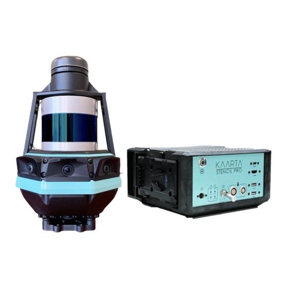
Congratulations on your purchase of Kaarta Stencil Pro. This document serves as a guide to get you quickly up and running with Stencil Pro and its component parts – the scanner and controller/control pack. You will learn to operate the system, familiarize yourself with the user interface, utilize the GNSS, and perform post-processing functions. -
Page 3: Scope
The Stencil Pro controller is not water or dust proof and should be operated with some caution. Keep the controller out of extreme temperatures, such as below freezing (0°C or 32°F) or hot temperatures (above 35°C/95°F). Use the shipping case to protect Stencil Pro during transportation. -
Page 4: Serial Number
. The Stencil Pro serial number can also be found on the About tab of Device Settings, through the Stencil Pro UI. See About on page 22 for more information on identifying your Stencil Pro Serial Number via the Stencil Pro Main Gallery options. -
Page 5: Release Notes
Import Scan An Import Scan feature has been added, allowing for more seamless importing of zip files that have been downloaded from Kaarta Cloud or other locations. Addition of Tooltips have been added to post-processing fields and Processing Tooltips tasks for improved transparency. -
Page 6: Table Of Contents
Release Notes ..........................5 Chapter 1 ............................8 Getting Started ........................... 8 What’s In The Box ........................8 Identifying Stencil Pro Components ..................8 Front of Scanner ........................8 Back of Scanner ........................8 Front of Controller ........................9 Side/Top of Controller ......................9 External Scanner Components ..................... - Page 7 Chapter 7 ............................ 111 Troubleshooting ........................111 Verify Scanner Is Receiving Images ..................111 Verify GNSS Is Communicating ................... 112 IP Addresses for Stencil Pro ....................114 W W W . K A A R T A . C O M...
-
Page 8: Chapter 1
C H A P T E R 1 G E T T I N G S T A R T E D W H A T ’ S I N T H E B O X 1. Scanner, with 4. Vehicle and Hand Carry Umbilical Cables a. -
Page 9: Identifying Stencil Pro Components
I D E N T I F Y I N G S T E N C I L P R O C O M P O N E N T S F R O N T O F S C A N N E R GNSS ANTENNA ANTENNA BRACKET 32-LINE SCANNER... -
Page 10: Front Of Controller
F R O N T O F C O N T R O L L E R USB-C PORT SCAN BUTTON HDMI PORT USB-A PORTS SHORE POWER CONNECTOR SCANNER DATA CONNECTOR LED STATUS LIGHTS SCANNER POWER CONNECTOR POWER SWITCH S I D E / T O P O F C O N T R O L L E R AIR VENTS V-MOUNT BATTERY PLATE BATTERY RELEASE... -
Page 11: External Scanner Components
Scan Button Start Scanning Push the Scan button to begin scanning. The LED ring around the button turns from blue to green or teal when Stencil Pro scanning has started (takes approximately 4-5 seconds). Stop Scanning To stop scanning, push the Scan button. The LED ring around the button turns from green/teal to yellow while saving, then returns to a blue ready state. - Page 12 FAST BLINK SOLID (1.0S) (0.5S) (0.1S) Scanner Booting Scanner Successfully Booted White Scanner Initializing Kaarta Software Kaarta Software Ready < 6 Satellites Ready >= 6 Satellites Blue Ready to Scan, Scanning, GPS Lock GPS Lock < 6 Satellites < 6 Satellites...
-
Page 13: External Controller Components
Scan Button Start Scanning Push the Scan button to begin scanning. The LED ring around the button turns from blue to green or teal when Stencil Pro scanning has started (takes approximately 4-5 seconds). Stop Scanning To stop scanning, push the Scan button. The LED ring around the button turns from green/teal to yellow while saving, then returns to a blue ready state. - Page 14 C O N T R O L L E R L E D S T A T U S L I G H T S L A Y O U T Left Right Battery Battery (BAT 1) (BAT 2) Internal Scanner Compute Power...
-
Page 15: Chapter 2
Stencil Pro UI, connect the supplied wireless keyboard/mouse, using the controller’s USB- A ports. Connect the iPad to Stencil Pro by inserting the HDMI Wi-Fi dongle into a Stencil Pro HDMI port and selecting the internal PCI Wi-Fi Hotspot Active option under wireless settings. -
Page 16: Supply Power To The Controller
Leave the Power On/Off Switch in the down or off position until the scanner’s power and data connections are configured. Caution: Stencil Pro does not charge your V-Mount batteries when connected to electrical/shore power. Use a compatible AC charger or power supply to recharge batteries when drained. - Page 17 Once the device boots, the Stencil Pro UI automatically opens and displays on the iPad (Figure 2). For more information about the Stencil Pro UI, see Main Gallery on page 17. You are now ready to start collecting data to capture your scene. See the following chapter, Stencil Pro Operation for complete scanning instruction.
-
Page 18: Chapter 3
In addition, Stencil Pro performs post-processing data functions such as sharpening, filtering, and colorization of the point cloud. - Page 19 Import Scan Use Import Scan to import a Contour scan (.ply) or a Stencil Pro scan as a zip file. Jobs Queue If you run post-processing on multiple scans, they can be queued to run unattended in the Jobs Queue.
- Page 20 • S T A T U S The Status tab displays the status (active or inactive) of Stencil Pro’s main components; IMU, and color camera (active or inactive), as well as the status of the scanner (on or off) (Figure 6).
- Page 21 Refresh All allows you to restart all of Stencil Pro’s main services, including the IMU, • color camera, and scanner. The status of the IMU and color camera are displayed as either Active Waiting. The status of the scanner is displayed as either or Off.
- Page 22 Max Parallel Jobs sets the maximum number of jobs (up to 10) that you can run in • parallel on Stencil Pro. Script jobs, such as processing, cannot be run in parallel. However, tasks such as uploading and copying can be set to run concurrently.
- Page 23 Figure 8: The Help tab of Stencil Pro System Settings. A B O U T The About tab lists the lifetime scanning duration, lifetime points collected, device serial number, current software version, firmware version, date the software was last updated, and the date the unit was last checked for an update (Figure 9).
- Page 24 It is important to occasionally connect the device to the internet, such as through the internal Wi-Fi or a USB to ethernet converter. Upon booting Stencil Pro, the system will automatically check for software updates. You can use the Check for Updates button to manually search for available software upgrades as well.
- Page 25 window displays, where you can name your newly created album. Click Okay to create album (Figure 11). Figure 11: Create a New Album. Scan Tip: Albums cannot be nested, so establishing a methodology for organizing albums by customer or location, combined with unique folder titles, goes a long way to keeping your scans organized.
- Page 26 S c a n F o l d e r s o n M a c h i n e As an alternative to the Stencil Pro UI, all scan data files can be accessed in the Desktop/recordings folder (Figure 13). The desktop folder scheme mirrors what is shown in the UI.
- Page 27 “keyposes,” “maps” (or post-processed files), and “raw data” (unprocessed files) (Figure 14). The keyposes folder stores all keyposes, including the keypose.txt file and associated Keyposes are not currently available for Stencil Pro and will be released at a rviz images.
- Page 28 The table below lists files and folders found within each main folder scan and indicates whether the file is an artifact of post-processing. In addition, there are several files that Stencil Pro uses repeatedly throughout the folder structure of a scan; you may see these scan_info.txt scan_info.yaml...
- Page 29 DESCRIPTION Main Scan Folder cover.jpg The cover photo image for the current scan. logXXXXXXXXX.txt Log files of uploads to Kaarta Cloud from the device. scan.log Detailed information available during the scan. Provides a record of the ubuntu terminal window for the scan in text file format.
- Page 30 Corrected/aligned GNSS data as point cloud. loopclosure_options.yaml Yaml file of loop closure parameters settings used in alignment. trajectory.ply Trajectory of the Stencil Pro, in point cloud format, post alignment. trajectory.kml KML file of the corrected/aligned trajectory. trajectory_GPS.kml Corrected trajectory of the GNSS antenna as kml.
- Page 31 L I S T O F M A P P I N G F I L E S trajectory.ply Trajectory of the Stencil Pro, in point cloud format, after being filtered. color_options.yaml Yaml file of parameter settings used during color projection.
- Page 32 Stencil Pro. The files should be recognized on the second Stencil Pro device once the scan folder has successfully copied to the desktop. The scan should be recognized by Stencil Pro and display in the Main Gallery.
-
Page 33: System Information
S Y S T E M I N F O R M A T I O N From the Main Gallery, you can view Stencil Pro system information. These elements are accessible throughout the Stencil Pro UI and are displayed on all screens (Figure 19). - Page 34 Stencil Pro ships with a 1TB Solid State Drive (SSD). A warning is displayed in the UI if the In general, 1 minute of remaining space is less than 15% of the total available space.
- Page 35 Scan Tip: It is important to establish a data management policy early on where data is transferred from Stencil Pro to either Kaarta Cloud or a backup system. Consider keeping a blank USB 3.0 external drive with your Stencil Pro when you need to make room for more scanning while in the field.
- Page 36 GNSS input, see Getting Best Results on page 100. W i r e l e s s Stencil Pro has the capability to establish a Wi-Fi connection to a wireless network. With software release SP21.02.1, Stencil Pro can also be used as a hotspot in conjunction with its internal wireless adapter.
- Page 37 NTRIP, see Getting Best Results with GNSS on page 101 for complete details. INTERNAL WI-FI WI-FI NETWORKS Figure 21: Connect to a Wi-Fi Network (left) or utilize Stencil Pro as a Hotspot (right). W W W . K A A R T A . C O M...
-
Page 38: Basic Scanning
Scan button once, or by pushing the Start Scan button in the top right corner of the Stencil Pro UI Main Gallery (Figure 22). If scanning by the former two methods (via the scanner’s or controller’s Scan button), Stencil Pro will begin to collect data immediately, using the color adjustment settings from the previous scan. - Page 39 (These options are not available if scanning thru the scanner only). The scan’s cover photo (the initial photo taken at start- up) is shown. The status of Stencil Pro’s IMU is shown in the lower right-hand corner of green...
- Page 40 On the iPad, you should see data being captured with >= 6 with < 6 and a point cloud building within the Stencil Pro UI. Once satellites satellites W W W . K A A R T A . C O M...
- Page 41 Ubuntu menu. If you are receiving data in the Stencil Pro UI, but the data is twisting or shows data jitter, you should stop the scan immediately. After the scanner returns to...
- Page 42 a blue ready state, power cycle the scanner by unplugging the power connection from the controller. From the Scanning screen, you can change viewing options, such as pointcloud orientation and zoom capabilities. The Scanning screen is comprised of three sections: Scanning Menu, Scanning Status bar, and the Scan View (Figure 25).
- Page 43 Some tools are available when the Panoramic Camera view is enabled. See Scan View on page 45 for more information about Stencil Pro’s two views (the Map Data view, and the Panoramic Camera view). For example, with the Panoramic Camera view in focus or enlarged, tools specific to the operation of the four panoramic cameras will become available (Figure 27).
-
Page 44: Scanning
Cameras Cameras Shown in the lower left corner of the screen, the window displays a panoramic image stitched from Stencil Pro’s four color cameras. Press to change status to Hide Cameras. Hide Indicates that map view is displayed without panoramic Cameras camera available. - Page 45 TOTAL POINTS COLLECTED CONFIDENCE METER ELAPSED TIME Figure 28: Scanning Status Bar elements labeled. S C A N N I N G S T A T U S B A R E L E M E N T S Elapsed Time Time elapsed during current scan session.
- Page 46 S c a n V i e w Stencil Pro enables you to switch between two available screens or views of the scan, the Map Data or pointcloud view, and the Panoramic Camera view. The top right button on...
-
Page 47: Stop Mapping
(see Figure 29). The Panoramic Camera view shows a live stream from Stencil Pro’s four color cameras. While the Panoramic Camera view is enlarged, the Map Data view is displayed in the lower left-hand corner of the UI. -
Page 48: Scan Details
32). The five tabs on the Scan Detail screen are as follows: Overview, File Mgmt., Image Mgmt., Processing, and Kaarta Cloud. The Rename and Delete buttons at the top right of the Scan Details screen remain active on each tab of the Scan Detail screen. - Page 49 Selecting the Rename button allows you to change the Album or file names using the wireless keyboard, or a graphical keyboard using the Stencil Pro touchscreen or connected keyboard. Delete The Delete button either moves the file to the Trash Bin or permanently deletes the current scan, based upon which setting is chosen in the Scanning tab of Device Settings.
- Page 50 For more information about useful tools within CloudCompare, please see Kaarta’s Using CloudCompare manual, which can be found on your Stencil Pro documentation drive. Figure 33: File Management tab of Scan Details.
- Page 51 The Image Management tab shows all color images captured during scanning (Figure 34). Scans are saved in the recordings folder on Stencil Pro desktop, like previous Stencil versions. To view your images, navigate to your scan in the Stencil Pro desktop/recordings folder.
- Page 52 Even when observing vehicle-mount best practices, parts of the componentry or traces of the vehicle roof may be captured by the color cameras. Stencil Pro has a built-in tool to This tool works best when there is a section in remove obstructions from the imagery.
- Page 53 last point. Once the exclusion zone is completed, select Save Yaml to formalize the polygon to yaml for use during processing. Figure 35: Create image exclusion zone. Once the areas to remove are highlighted, select Save Yaml to define the polygonal area for exclusion from processing.
- Page 54 (Figure 37). Note: Scans are organized in Kaarta Cloud by Job, not by scan. A Job is defined as the container for your scan (or multiple scans), and includes any associated or linked assets, notes, processed files, etc.
- Page 55 Initiates the uploading process. The Jobs Queue displays the progress of the upload. Upload allows you to add your scan to an existing job or create a new Kaarta Cloud job. select the radial button beside Add to Existing Job. Existing jobs display in the drop-down menu below the button.
- Page 56 Figure 38: Kaarta Cloud tasks in Jobs Queue. In addition to uploading to Kaarta Cloud, you can also compress and/or copy your scan to another location by selecting the Compress Copy tab at the top right side of the screen (Figure 39).
- Page 57 Figure 39: Compress Copy. W W W . K A A R T A . C O M...
-
Page 58: Chapter 5
Stencil datasets, adding a substantial amount of clarity and understanding to point cloud data. The Stencil Pro UI offers the user unique customization for post-processing data. You have the option to perform actions either individually or as a series of tasks that will run sequentially. - Page 59 ADVANCED VIEW Figure 40: Processing tab of Scan Details, Advanced View. A d v a n c e d V i e w Within the Advanced View of the Processing tab, there are two main columns to select the Process (left column) and the Preset for that process (right column) (Figure 41). To add or change the process in the left dropdown menu, click in the menu box and select from the list of processes available.
- Page 60 Once a process is selected, presets for that process become available for selection in the right-hand column of Advanced View. Note: You can create your own individualized presets and settings for Stencil Pro. The presets described in this manual refer to those that are included with Stencil Pro software.
- Page 61 Standard View on page 95 for more details. Runs the processing of a scan according to the selected options above. Processes available on Stencil Pro include align, fine align, color, convert to LAS, filter, GNSS correct, create image poses, playback, prefilter, relabel panoramas, stitch panoramas, subsample, or zip.
- Page 62 Convert to Convert to LAS Default settings for converting a point cloud to an LAS file. Filter Filter by All Applies several Kaarta- certified filters to the data. GNSS CORS_AUS Use the CORS network data Correct provided by the Geoscience Australia GNSS data archive for GNSS correction.
- Page 63 Raw Data Zip raw data (bag file) only. Stencil Pro was specifically designed to provide a complete toolbox for processing of your scan data, taking you from a collection of points to an accurate and visually stunning 3D dataset. In a modular fashion, your processing workflow can be customized, saved, and reviewed through the user interface.
- Page 64 P l a y b a c k The lidar on Stencil Pro operates at 10 hz, however to operate in real time, Stencil Pro processes lidar data at 5 Hz. Normally, this data is dense enough for most applications and is the maximum density available in real time.
- Page 65 There are situations where you may wish to generate maps from multiple scans, however. This is done by first creating a baseline map that Stencil Pro uses as a reference map while collecting more detailed maps, extending maps, or building maps of more complex environments.
- Page 66 After creating the reference map, select the Localization Map by tapping into the ellipse. If you are using a map you have previously processed on Stencil Pro, browse and select it. You can also select an external map that you’ve imported onto Stencil Pro. See Import Scan under the Main Gallery Menu on page 17 for more details.
- Page 67 P L A Y B A C K S E T T I N G S Starting Time You have the option to skip portions of a scan if you had issues at the (seconds) start of the data collection or had an extended pause during initialization.
- Page 68 If you adjusted any of the default configuration settings while on the Edit Preset screen, you have the option to either save the settings as a new preset (to be run again at a later time) or, if you do not want to save the current configuration, you can discard the parameter settings and return to the Advanced View screen to initiate the processing task.
- Page 69 NAME NEW PRESET Figure 46: Save new preset. If you attempt to return to the Advanced View screen from Edit Preset without saving changes, you will be prompted to either save the settings as new preset or discard all changes (Figure 47). Click Yes to name and then save your changes as a new preset or No to return without saving.
- Page 70 Having returned to the Advanced View Processing screen, click Run at the bottom of the UI to start playback. After playback is initiated, the Jobs Queue displays, showing the progress of your processing (Figure 48). If GNSS data was collected during initial scanning, the GNSS status of the playback is shown in the GNSS Status window.
- Page 71 Figure 50: View scan after playback. C o l o r Stencil Pro is equipped with four 8-megapixel color cameras which capture high resolution 360° imagery, enhancing an already comprehensive 3D model by creating a visual record of current project conditions, as-built environments, and corridor mapping projects.
- Page 72 This adjustment may be needed when vehicle-mounted, depending on speed of travel. Set to -0.1 up to +0.5, with the higher end of the spectrum used for faster vehicle speeds. It is recommended to process first with the default latency values, then adjust as needed by reviewing the colorized point cloud, then running color additional times to correct for any latency.
-
Page 73: Configuring Ntrip
G N S S C o r r e c t Stencil Pro uses simultaneous mapping and localization in GNSS-denied environments. When GNSS signal is available, however, Stencil Pro has an integrated Trimble GNSS receiver to achieve best-in-class, low-drift accuracy while mapping over longer ranges. - Page 74 Color configuration settings (Figure 53). Further editing may not be needed or warranted if the correct preset was chosen. For example, Stencil Pro’s integrated Trimble GNSS receiver is configured to use the BINEX (binary exchange) file format. Therefore, for processing Stencil Pro datasets, the ROVER Importer file should be kept at USER_BINEX.
- Page 75 The BASE Importer file corresponds to the output configuration of your base station receiver, whether a subscription-based corrections network or a standard base station. If the correct GNSS Correct preset was chosen in the previous step, no additional changes should be made. The RTKLib (First and Last) Elevation Mask can assist with eliminating satellites with atmospheric errors and signal degradation.
- Page 76 G N S S C O R R E C T S E T T I N G S ROVER Importer For processing Stencil Pro datasets, the rover file should be kept at created on other devices USER_BINEX. However, if importing datasets for processing on Stencil Pro, the rover file will need adjusted according to file format of the roving device (RINEX, UBLOX, RTCM3, or PLAIN).
- Page 77 Overlapping trajectories are not necessary if GNSS data has been recorded by Stencil Pro for your scan. Drift corrections can be done even if you did not start and stop at the same place.
- Page 78 Figure 54: Align presets. A L I G N P R E S E T S GNSS_and_loops Align with both GPS data and loop closure techniques. GNSS_only Align using GNSS data and no loop closure. Loops_only Align with loop closure techniques only. Once an Align preset is chosen, click the Edit button to the right of the preset to change Align configuration settings, including changing the minimum point spacing, adjusting the minimum GNSS fix quality of points, and loop closure ranges (Figure 55).
- Page 79 250 to do a rough approximation with faster results and see that your other parameters are set correctly before doing a final alignment with closer points. The Minimum Fix Quality uses the GNSS fix quality to eliminate GNSS points where the quality is too low for use in alignment.
- Page 80 user. If left blank, the geo-registered map's coordinates will be referenced to the local UTM zone, based on latitude/longitude at the start of the scan. EPSG codes can be found here. The Scale Correction Factor in essence magnifies or shrinks the entire scan by a specified value before alignment is performed.
- Page 81 A L I G N S E T T I N G S Max HDOP value Uses the Horizontal Dilution of Precision (HDOP) error estimate to eliminate GNSS points where the quality is too low or noisy for use in alignment.
- Page 82 A L I G N S E T T I N G S Scale Correction The Scale Correction Factor can be used to scale the entire scan by a Factor (use 0.9996 for specified value before alignment is performed. This can be helpful to UTM cc) correct for lidar calibration inaccuracies especially in multi-kilometer scans.
- Page 83 F I N E A L I G N S E T T I N G S Minimum GNSS Fix Uses the GNSS fix quality to eliminate GNSS points Quality where the quality is too low for use in alignment. You can choose between fix quality of Automatic, GPS (1), DGPS (2), RTK Float (5) and RTK (4), in order of accuracy from least accurate GPS to most accurate.
- Page 84 Run Sharpening compresses flat surfaces and reduces the repeatability blur of the lidar. Kaarta Clean calculates outliers, noise, and other unwanted data in the point cloud. Filtering will remove these points from your dataset. The Mean K is the statistical outlier calculation which computes the average distance of each point to its neighbors (considering k nearest neighbors for each).
- Page 85 Normals can be removed in the Filter process by enabling Kaarta Filter 1. See Filter on page 85 for more details. Run Sharpening Check box to run sharpening on dataset.
- Page 86 Note: You must use Pre-Filter prior to Filtering your data, for best results. There are four filters that can be applied, Kaarta Filters 1-4 (Figure 59). Adjustments can be made to each of the four filters by editing the thresholds. In general, lower thresholds...
- Page 87 The threshold is in meters. Kaarta Filter 2 Check box to remove spurious points or statistical outliers calculated in the Pre-Filter task under Kaarta Clean. See Pre-Filter on page 81 for more details. Filter 2 removes points above a standard deviation threshold.
- Page 88 F I L T E R S E T T I N G S Start time (seconds) If filtering by time from start, add the number of seconds for the minimum time to keep. 0 keeps all points. End time (seconds If filtering by time from start, add the number of seconds for the maximum time to keep.
- Page 89 Figure 60: Stitch Panoramas presets. S T I T C H P A N O R A M A S P R E S E T S 10000pixels Width of stitched images can be set to 10,000 pixels (with a corresponding height of 2000 pixels). 4000pixels Width of stitched images can be set to 4,000 pixels (with a corresponding height of 800 pixels).
- Page 90 Figure 61: Stitch Panoramas settings. S T I T C H P A N O R A M A S S E T T I N G S Width (pixels) Sets the width of the stitched panorama (in pixels). Height (pixels) Sets the height of the stitched panorama (in pixels).
- Page 91 Note: Both Image Poses and Relabel Panos are already embedded in the Colorization process. If there is a change in alignment, such as during GNSS Correct or Align, you can choose to rerun these two processes to update the change in poses and correct the metadata of the images.
- Page 92 A subsampled point cloud retains all the features of its source or input cloud (scalar fields, colors, normals, etc.). There are four methods of subsampling available on Stencil Pro: Percent, Random, Spatial, and Octree (Figure 64). Subsampling by a Percent will reduce the point cloud by a percentage of total points.
- Page 93 Figure 64: Subsample presets. S U B S A M P L E P R E S E T S Percent (10_percent) Retains 10% of the total points. Random Subsamples to 30 million random points. (30_million_points) Spatial (5cm) Downsamples the pointcloud to 1 point within a 5cm diameter.
- Page 94 Figure 65: Subsample settings. S U B S A M P L E S E T T I N G S Subsampling Method Select subsampling method from drop-down menu: Percent, Random, Spatial or Octree. Parameter If percent, adjust parameter by changing decimal value or 10% to percent of points remaining (default is 0.10 If random, adjust parameter by changing number of...
- Page 95 There is one setting that can be abled/disabled for Convert to LAS. Click the Edit button next to the Convert to LAS preset to view the option to convert only the pointcloud (true) or to convert all pointscloud and trajectories (false; Figure 67). Click Run to proceed. Figure 66: Convert to LAS preset.
- Page 96 Z i p You can zip or compress your Stencil Pro files by using the Zip function. You have the choice of either compressing your processed map or the scan’s raw (unprocessed) data. No settings can be modified (Figure 68). Select Zip and click Run to proceed.
- Page 97 S T A N D A R D P R O C E S S I N G The Standard Processing procedure lists the recommended sequence for processing data on Stencil Pro. To see the details of the Standard Processing procedure, check the Advanced View box to display each step (Figure 70).
- Page 98 Figure 70: Standard Processing procedure. J o b s Q u e u e If you run post-processing on multiple scans, they can be queued to run unattended in the Jobs Queue. To view pending scans, select the Pending Jobs button in the lower right of the UI.
- Page 99 Figure 71: Jobs Queue J O B S Q U E U E O P T I O N S Restart Job Select a job in the queue and restart post-processing. Cancel Job Select a job in the queue and cancel it. Move to Top Select a job in the queue and change its order.
- Page 100 Figure 72: Detailed output of current processing task. W W W . K A A R T A . C O M...
- Page 101 Keep in mind that some of the data you will need to complete the PPK process is provided by government entities and may take 24-48 hours. In addition to PPK, Stencil Pro also supports Network Transport of RTCM via Internet Protocol (NTRIP) for real-time differential correction. NTRIP is an open standard protocol that sends correction data using the internet via a cellular modem (generally a cell phone or hot spot).
- Page 102 Another source of poor fix quality could be a bad connection with between the Trimble device and Stencil Pro. Establish that the GNSS is communicating with Stencil Pro, by following the Verify GNSS Is Communicating troubleshooting steps on page 112.
- Page 103 Verify that you initially acquire a signal prior to entry, and that you can reacquire signal after exiting an obscured area. At a minimum, make sure to anchor your trajectory with good quality GNSS at beginning and again at end. Any points that can be acquired during scanning, even intermittently, can assist with PPK correction.
- Page 104 Next, select the hot spot device or phone you are using to connect to the internet under Stencil Pro’s available wireless networks (Figure 75). If required, provide a password, and click the Connect button. See Wireless on page 35 for assistance with connecting to an available wireless network, if needed.
- Page 105 To configure the Trimble device for NTRIP, you will need to log in to the Trimble hardware administration page. Open a web browser from the Stencil Pro desktop and proceed to 10.20.27.3 in the address (Figure 76). Take every precaution when changing settings on the Trimble administration page;...
- Page 106 Figure 76: Trimble Admin page. Select I/O Configuration in the main menu, along the left side of the screen. The I/O Configuration page displays (Figure 77). From here, you will enter your NTRIP account information. Click the NTRIP Client 1 heading under Type to display the settings (Figure 78).
- Page 107 Caution: Do not change any of the other port information! The TCP/IP ports have been configured for the integrated Trimble PPK and should not be adjusted (see Figure 77). Figure 78: NTRIP Client settings. N T R I P C L I E N T S E T T I N G S Status Indicates the current status of the NTRIP connection.
- Page 108 A n t e n n a C o n f i g u r a t i o n Log into the Trimble administration page. Open a web browser from the Stencil Pro desktop and proceed to 10.20.27.3 in the address (see Figure 78 above; see Trimble Administration on page 104 for information about user/password).
- Page 109 Figure 79: Antenna Configuration settings. U S I N G D A T A F R O M Y O U R O W N B A S E S T A T I O N The process for importing base station files to produce a PPK trajectory are the following: I m p o r t F i l e s t o S t e n c i l P r o Ensure you are importing the correct base station observation and satellite navigation files corresponding to the entire time period during which the scan was captured.
- Page 110 Desktop/recordings/*your dated scan folder/raw_data/base_station / (Figure 80). See Figure 81 for an example of assorted base station files copied to the Stencil Pro base station folder. In this example, the letter “e” indicates the files covered UTC hour 4 (i.e.
- Page 111 Figure 81: Imported base station files. Note: Not all base station files are identical and Kaarta has not tested with all formats or manufacturers. Please contact Kaarta if there are any issues or questions with files from your base station.
- Page 112 C H A P T E R 7 T R O U B L E S H O O T I N G V E R I F Y S C A N N E R I S R E C E I V I N G I M A G E S Prior to mapping, verify that the scanner is receiving images.
- Page 113 V E R I F Y G N S S I S C O M M U N I C A T I N G The GNSS status window displays in the lower left corner of the Stencil Pro UI. The color of the box and corresponding satellite icon denote the status of the scanner’s current...
- Page 114 Figure 82: Trimble Admin page. Select I/O Configuration in the main menu, along the left side of the screen. The I/O Configuration page displays (Figure 83). Make sure both TCP/IP connections are green, indicating that they are active. Figure 83: I/O Configuration information on the Trimble admin page. W W W .
- Page 115 Warning: If settings are correct, but the system continues to Wait for GNSS data, the scanner needs to be restarted. Power cycle the scanner by unplugging the power connection from the controller. I P A D D R E S S E S F O R S T E N C I L P R O I P A D D R E S S E S 10.20.27.1 Controller...
- Page 116 S T E N C I L P R O U S E R G U I D E U G - S 3 - 2 1 . 0 2 . 1 - 0 0 2 - 0 8 2 2 K A A R T A E N G I N E U .
Need help?
Do you have a question about the STENCIL PRO and is the answer not in the manual?
Questions and answers