Table of Contents
Advertisement
Quick Links
Advertisement
Table of Contents

Subscribe to Our Youtube Channel
Related Manuals for kaarta Stencil Pro


Summary of Contents for kaarta Stencil Pro
- Page 1 S t e n c i l P r o V e h i c l e M o u n t : A s s e m b l y , S t o w a g e , & U s e V M G - S 3 - 2 1 .
-
Page 2: Introduction
I N T R O D U C T I O N In addition to using Stencil Pro as a handheld or pole-mounted scanner, the system can be mounted to a vehicle for rapid, accurate and visually stunning reality capture in urban areas. -
Page 3: Table Of Contents
C O N T E N T S Introduction ............................Stencil Pro Vehicle Mount ........................ Vehicle Mount Components ......................Assembly Instructions ........................Stowed Assembly ........................Assemble Mount ......................... Stowage Procedure for Shipping/Transport ................Mounting Instructions ........................ Placement of Mount on Vehicle Roof .................. -
Page 4: Stencil Pro Vehicle Mount
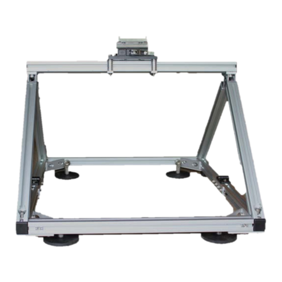
S T E N C I L P R O V E H I C L E M O U N T V E H I C L E M O U N T C O M P O N E N T S Tools Required for Assembly/Disassembly: 1. -
Page 5: Assembly Instructions
Caution: Whether using the Kaarta vehicle mount (as described here) or another setup, it is crucial that the vehicle mount utilized be properly secured. Always confirm that Stencil Pro is secured to the mount, and the mount is firmly fastened to the vehicle. -
Page 6: Assemble Mount
STOWED UPPER VEHICLE MOUNT ASSEMBLY STOWED VEHICLE MOUNT BASE ASSEMB LY Figure 3: Stowed Upper Vehicle Mount Assembly (top) and Stowed Vehicle Mount Base assembly (bottom). A S S E M B L E M O U N T S t e p 1 : A s s e m b l e t h e S t o w e d V e h i c l e M o u n t B a s e 1. - Page 7 2. Remove the four (4) M8 Fasteners, split lockwashers, and flat washers from each corner of the Vehicle Mount Base Assembly and set aside (Figure 4). 3. Using a 4mm hex allen key, loosen all sixteen (16) M6 x 16mm long button head fasteners securing the four (4) Base Reinforcement plates to the Vehicle Mount Base Assembly.
- Page 8 PIVOT JOINT (4X) UPPER SUPPORT ARM (4X) M5 X 10MM LONG FLAT HEAD SCREW (8X) STOWED UPPER VEHICLE MOUNT ASSEMBLY Figure 6: Upper Vehicle Mount Assembly support arm pivot fastener location. 2. Starting with the one of the outside stowed Upper Support Arms, use a 6mm hex allen key to loosen one (1) M8 X 16mm long socket head fastener that secures the pivot joint to the top cross rail.
- Page 9 M8 X 16MM LONG SOCKET HEAD FASTENER TOP CROSS RAIL OUTSIDE UPPER SUPPORT Figure 8: Upper Vehicle Mount Assembly first outside support arm deployment. 4. Repeat 2 and 3 above with the stowed outside Upper Support Arm at the other end of the Top Cross Rail (Figure 9).
- Page 10 OUTSIDE UPPER SUPPORT TOP CROSS RAIL M8 X 16MM LONG SOCKET HEAD FASTENER Figure 9: Upper Vehicle Mount Assembly second outside support arm deployment. 5. Repeat steps for the remaining two (2) stowed inside Upper Support Arms. Once all four (4) Upper Support Arms have been rotated outward, ensure that all four (4) Upper Support Arm pivot joints are at the end of the Top Cross Rail and each pivot joint alignment tab is up against the end caps.
- Page 11 M5 X 10MM LONG FLAT HEAD SCREW (8X) UPPER VEHICLE MOUNT ASSEMBLY M5 ADAPTER PLATE (8X) UPPER SUPPORT ARM (4X) Figure 10: Upper Vehicle Mount Assembly operational support arm deployment. 6. Tighten all eight (8) of the M5 flat head fasteners in the pivot joints just enough to still allow rotation of the arms on the pivots with some resistance.
- Page 12 VEHICLE MOUNT SET SCREW STOP (4X) Figure 11: Stencil Pro Vehicle Mount Assembly operational configuration. 8. Tighten the eight (8) M5 flat head fasteners in the pivot joints of the Upper Support Arms to lock the Upper Vehicle Mount Assembly in place.
-
Page 13: Stowage Procedure For Shipping/Transport
S T O W A G E P R O C E D U R E F O R S H I P P I N G / T R A N S P O R T S t e p 1 : R e m o v e U p p e r V e h i c l e M o u n t A s s e m b l y 1. - Page 14 M8 HARDWARE M8 HARDWARE VEHICLE MOUNT BASE ASSEMBLY Figure 13: Upper Vehicle Mount Assembly hardware re-installation. S t e p 2 : S t o w t h e V e h i c l e M o u n t B a s e A s s e m b l y 1.
- Page 15 2. Slide each Base Reinforcement plate until the entire plate is in its stowed position on the Front Side Rail at the approximate locations shown in Figure 15. Tighten all sixteen (16) M6 button head fasteners so all four (4) reinforcement plates are secure to the front side rail.
- Page 16 S t e p 3 : S t o w t h e U p p e r V e h i c l e M o u n t A s s e m b l y 1. Retrieve the Upper Vehicle Mount Assembly. Using a 3mm hex allen key, loosen all eight (8) M5 x 10mm long flat head fasteners that secure the four (4) Upper Support Arms to their corresponding pivot joints (approximately ½...
- Page 17 Figure 20. Arm must be clear of the adjacent pivot joint and be able to rotate freely. Rotate the arm and pivot 90 so the entire assembly is stowed in-line with top cross rail and the arm is resting on the Stencil Pro Mounting Plate as shown in Figure 20. PIVOT JOINT...
- Page 18 Figure 20: Stowage of first Upper Support Arm. 3. Using a 3mm hex allen key, tighten the two (2) M5 flat head fasteners in the pivot joint at this time. Leave the M8 socket head fastener loose in case it needs to slide to allow the adjacent pivot to rotate.
- Page 19 Figure 22: Final stowage of Upper Vehicle Mount Assembly. 6. Once all Upper Support Arms are stowed in position, secure the arms in the stowed position by tightening all four (4) M8 x 16 long socket head fasteners to secure arms to the Top Cross Rail.
-
Page 20: Mounting Instructions
M O U N T I N G I N S T R U C T I O N S After careful assembly and verification of all connection points on the vehicle mount, it can be used for vehicle scanning. See Error! Reference source not found. on page 24 for recommendations regarding vehicle mount placement and appropriate tilt or angle of the scanner for achieving best results. - Page 21 S t e p 3 : A t t a c h t h e S t e n c i l P r o t o M o u n t i n g P l a t e & C o n n e c t P e r i p h e r a l s 1. Attach Stencil Pro scanner to the Vehicle Mount mounting plate using the four (4) provided 1/4”-20 bolts with the cable connectors facing the rear of the vehicle (Figure 25).
- Page 22 Do not overtighten. 3. Connect Stencil Pro power and data cables to the corresponding connectors on the Stencil Pro scanner (see Stencil Pro User Guide for proper setup instructions). 4. The cables can be connected and tightened by hand and should not require any tools.
- Page 23 3. Pull to the side of the road to a complete stop and check structural integrity of mount and system. Check all fasteners for the Stencil Pro controller attachment and fasteners on the vehicle mount itself. W W W . K A A R T A . C O M...
-
Page 24: Scanning Angle And Coverage
S C A N N I N G A N G L E A N D C O V E R A G E The Stencil Pro vehicle mount is tilted slightly (between 5 and 10 degrees), which has been found by Kaarta personnel to provide for more comprehensive point cloud capture and allow for better upward image capture. -
Page 25: Image Exclusion Zones
10 images, the actual image at index 0 may vary depending on the scan. As shown in Figure 28, parts of the vehicle’s roof and Stencil Pro mount can be seen in the imagery. You will create a polygon to highlight the areas for removal by left clicking directly onto the image. - Page 26 The following keys are used to control: s Save and Exit • e exit without saving • n switch image • c clear polygon • u undo last click • Figure 28: Image Exclusion interface. W W W . K A A R T A . C O M...
- Page 27 Figure 29: Highlighted exclusion area. Figure 30: Original imagery (top), highlighted exclusion zones (bottom). W W W . K A A R T A . C O M...
- Page 28 Once the areas to remove are highlighted, click “s” to see the points of the exclusion zones listed in the terminal window. 0,0 is the upper left of the image (Figure 31). Figure 31: Exclusion polygon. This is also written to the active ROS environment so after this is done the color process can be run and it will apply the exclusion zones.
- Page 29 S T E N C I L P R O V E H I C L E M O U N T A S S E M B L Y , S T O W A G E , & U S E V M G - S 3 - 2 1 .
Need help?
Do you have a question about the Stencil Pro and is the answer not in the manual?
Questions and answers