Table of Contents
Advertisement
Quick Links
Advertisement
Table of Contents

Related Manuals for Techsis SL-224-H-P300


Summary of Contents for Techsis SL-224-H-P300
- Page 1 User Manual SL-224-H-P300 Version 1.0 May 2021...
- Page 2 SL-224-H-P300 Installation manual introduction The Product installation manual mainly describes SL-224-H-P300 PoE switch hardware features, installation methods, and precautions during the installation This manual includes the following chapters: Chapter 1: Product Introduction. Briefly describes the basic features, Detailed hardware &...
-
Page 3: Chapter 1: Product Introduction
SL-224-H-P300 Chapter 1: Product Introduction 1.1 Products description SL-224-H-P300 is managed PoE switch for security transmission and WIFI coverage, meet the need of PoE power supply for WIFI AP, IP-camera, WIFI bridge, IP phones and other types of equipment. New generation of high-performance hardware and software platforms are used, providing flexible, cost-effective full Gigabit access and uplink ports, complete security mechanisms, improved ACL / QoS strategy and rich VLAN capabilities. -
Page 4: Hardware Specification
SL-224-H-P300 1.3 Product Software and Hardware Specifications Hardware specification Port Performance • 24 10/100 Mbps RJ45 ports • Forward mode: store and forward • 2 SFP fiber ports • Backplane bandwidth: 8.8 Gbps • 2 10/100/1000 Mbps RJ45 ports •... - Page 5 SL-224-H-P300 Software features Shortcut function Protocol standard • One key VLAN • IEEE 802.3: Ethernet media access • One key Exnted (1-8 port 250meters PoE control (MAC) protocol distance) IEEE 802.3i:10BASE-T Ethernet • • One key QoS (Video priority) •...
- Page 6 SL-224-H-P300 Safety features Multicast • Password protection • Support IGMP v1/v2 Snooping Support user access based on port number, • • Support static multicast IP address, and MAC address • Support for multicast VLAN • Support HTTPS, SSL V3, TLS V1, SSH •...
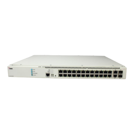
- Page 7 1. 4 product appearance ◼ front panel Contains indicator light, RJ45 port, SFP Port, DIP switch, RST button, Console port, as shown below ◼ indicator The SL-224-H-P300 indicator works as shown in the following table. Work Indicators Title Color Description...
- Page 8 AI power supply: Detect PD, power failure and restart dead equipment ❖ RJ45 Port SL-224-H-P300 with 24 10/100 Mbps PoE port , all ports support IEEE802.3af and IEEE802.3at standard When the switch mode of operation is CCTV mode, 1-8 port can support 250 meters power supply with 10Mbps speed rate ❖...
- Page 9 SL-224-H-P300 Back Panel Including: power socket, power switch, ground terminal ❖ Power socket A 100-240VAC 50/60 Hz power receptacle for accommodating the supplied power cord ❖ Power switch Turn on/off the power switch, control the power switch ❖ Ground terminal Please use the grounding wire to prevent lightning.
-
Page 10: Chapter 2 Installation
SL-224-H-P300 Chapter 2 Installation 2.1 Installation Precautions Note: To avoid improper use of equipment damage and personal injury, please observe the following precautions ◼ Installation safety precautions • The power should be kept off during the installation, while wearing anti-static wrist, and to ensure well touch between anti-static wrist and skin to avoid potential safety hazard;... - Page 11 SL-224-H-P300 ◼ Altitude Products with this logo are only for safe use in areas below 2000m altitude ◼ Dust-proof Dust on the switch surface will cause electrostatic adsorption, poor contact of the metal contacts. Although the device itself has done some measures in anti-static, but when the static electricity exceeds a certain intensity, it will still cause fatal damage to the electronic components on the internal circuit board.
- Page 12 2.2 Product installation 19-inch standard rack installation SL-224-H-P300 is designed according to the standard 19-inch rack size, you can easily install to the rack, the specific installation steps are as follows: First, Check rack grounding and stability;...
- Page 13 SL-224-H-P300 Third, place the switch in an appropriate place in the rack and be supported by the bracket. Screw the L-shaped bracket to the guide groove fixed on both ends of the rack to ensure that the switch is stable and horizontally installed on the rack Note:...
-
Page 14: Chapter 3: Hardware Connection
Do not connect the RJ45 port to the phone line 3.2 SFP Port connection SL-224-H-P300 SFP port only support Gigabit fiber module. Recommended use of standard SFP module products The process of installing a fiber module on a switch is as follows: First, grasp the optic fiber module from the side, insert it smoothly along the SFP port slot until the optic fiber module and switch are in close contact;... - Page 15 SL-224-H-P300 Second, confirm the Rx and Tx ports of the fiber module when connecting, insert one end of the fiber into the Rx and Tx ports correspondingly, ensure that the Tx and Rx ends of the interface are connected correctly and the other end of the fiber is connected to another device;...
- Page 16 SL-224-H-P300 Step 2: Manually changed the computer IP address to 192.248.254.X (X is 2 ~ 254), subnet mask is 255.255.255.0 Step3: Open computer's browser, type 192.248.254.1 in the address box, hit the Enter key Step4: Enter the default username and password “admin” and then click Login...
- Page 17 SL-224-H-P300 Chapter 4: packing list and recommendations for use 1.1 Open the package and check the following list carefully article Quantity Description switch power cable Switch power supply Hanging ear For rack mounting Warranty Card For after-sales maintenance Product manual Used to guide users to install switches 4.2 Suggestions for use...
- Page 18 SL-224-H-P300 Www.techs.is , Sales@techs.is :021-22371482 , :021-66402031...
Need help?
Do you have a question about the SL-224-H-P300 and is the answer not in the manual?
Questions and answers