Table of Contents
Advertisement
Quick Links
MODELS -
CONTENTS:
1.
2.
A.
AH TOTAL DISPLAY
B.
RESETTABLE DISPLAY
3.
A.
AH TOTAL DISPLAY
B.
RESETTABLE DISPLAY
D.
PRESET1 &2 DISPLAY
F.
STROKE 1 &2 DISPLAY
G.
STROKE 1 &2 CNT LEFT DISPLAY
H.
CYCLE COUNT 1 &2 DISPLAY
I.
SETUP DISPLAY
1.
2.
3.
4.
5.
6.
7.
8.
4.
5.
INSTALLATION DIAGRAM
6.
7.
WARRANTY, TERMS OF SALE
CHECK FOR FREE MANUAL UPDATES AT
JP Tech, Inc. Box 863 2286 Church Street, Unit C East Troy WI 53120
Phone (262) 642-7671 Fax (262) 642-7681
290-AH1
290-AHP2 STROKECOUNT PUMP CONTROLLER
(Models: P2-1/1, 1/2, 2/1, 2/2)
RELAY1 & 2 DISPLAY
RELAY 3 DISPLAY
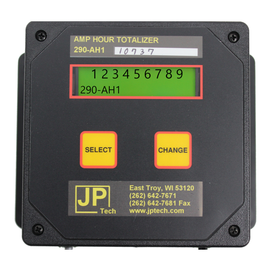
AMP HOUR TOTALIZER
P.3
P.3
P.3
P.3-6
P.3
P.3
P.3
P.4
P.4
P.4
P.4
P.4
P.4
P.5
P.5
P.5
P.5
P.5
P.6
P.6
P.6
P.6
P.6
P. 7-9
P. 10-11
P. 12
P.13
Rev 12/09/12
www.jptech.com
1
Advertisement
Table of Contents

Related Manuals for JP Tech 290-AH1


Summary of Contents for JP Tech 290-AH1
-
Page 1: Table Of Contents
INSTALLATION DIAGRAM P. 10-11 TROUBLE-SHOOTING P. 12 WARRANTY, TERMS OF SALE P.13 Rev 12/09/12 CHECK FOR FREE MANUAL UPDATES AT www.jptech.com JP Tech, Inc. Box 863 2286 Church Street, Unit C East Troy WI 53120 Phone (262) 642-7671 Fax (262) 642-7681... -
Page 2: General Information For Amp-Hour Based Meters
GENERAL INFORMATION FOR AMP-HOUR BASED METERS JP Tech’s Ampere-Hour meters incorporate several screen options in the Menu designed for ease of operation, information gathering, and programming. All models incorporate displays showing accumulated Ampere Hours or Ampere Minutes. A resettable Ampere Hour orAmpere Minute display is included. -
Page 3: Model 290-Ah1 Menu Operation
See ‘GENERAL INFORMATION’ MODEL 290-AHP2 MENU OPERATION This model incorporates everything the Model 290-AH1 has plus it can support 2 pumps with associated Presets and Stroke Counters and 1 Alarm output. All internal output relays are fused. Also, the status of the pump will be indicated in each of the main display screens by either a LmV (Low Millivolt signal = no accumaltion of Amp Hours) or P1 (Pump 1 = ON), P2 (Pump 2 = ON), or both pumps are on = P12. -
Page 4: Preset1 &2 Cnt Left Display
MODEL 290-AHP2 MENU OPERATION (Cont.) To the right is the PRESET1 screen. This screen PRESET1 is used to set the interval of Amp Hours before Pump1 is 000000 turned on. The PRESET2 screen operates the same way for Pump 2. [See “Calculating the Preset and Timer Value Needed”... -
Page 5: Shunt Size 1 & 2 Display
MODEL 290-AHP2 MENU OPERATION (Cont.) 1. To the right is the SHUNT SIZE #1 menu that is used SHUNT SIZE #1 to select the correct amperage rating of the rectifier, the 15,000H 50mV choice of amp hours or amp minutes, and the millivolt output of the shunt. -
Page 6: Stroke Timer
MODEL 290-AHP2 MENU OPERATION (Cont.) To the right is the STROKE TIMER display. This STROKE TIMER display tells the ALARM function how long, in seconds, to DISABLED wait before activating when a stroke count has not been received during the stroke count sequence. This alarm condition is different than the Low or High Alarm con- ditions stated above. -
Page 7: Appendix
APPENDIX A. CALCULATING THE PRESET AND TIMER VALUES NEEDED: The values you may need to run your metering system correctly can vary significantly. In most cases, the calculations are straightforward and only require a ratio of needed chemical additions per amp hour units. The following is a step-by-step example of how to derive a series of options for an actual situation. - Page 8 *** Break Down the Ratio to a Usable Level *** When rounding seconds, always go down to the next lowest whole second (e.g.; 50.9 sec. = 50 sec; 50.1 sec. = 50 sec.) When rounding amp/hours, always round up to the next whole amp/hour (e.g.;...
-
Page 9: Pump Setting Worksheet
B. PUMP SETTING WORKSHEET You will need the following information to use the Pump Settings Worksheet: Nominal Feed Ratio: (A)_____________ Gal. Per (B)_____________ Amp/Hours (As recommended by your chemical representative) Shunt Size: (E) _________________ Amps Actual Pump Vol: (G) _______________ ml. Per minute (Measured by You) Step 1. -
Page 12: Trouble-Shooting
TROUBLESHOOTING FOR AMP HOUR BASED METERS AMP HOUR ISSUES: NO AMP HOURS RECORDING WHEN RECTIFIER IS ENGAGED May have the leads from the twisted pair mV wire connected wrong at the shunt or analog amp meter in the remote. Reverse the leads of the Twisted Pair mV wire on the shunt or ana- log amp meter. - Page 13 JP Tech will repair or replace any defective part within a product at the sole discretion of JP Tech. If JP Tech should choose to supply a part to the •...
Need help?
Do you have a question about the 290-AH1 and is the answer not in the manual?
Questions and answers