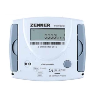
Summary of Contents for Zenner multidata
- Page 1 EnergyMetering multidata Installation and operating manual Electronic energy calculator for heat meters with 2 inputs/outputs optionally with M-Bus, RS 232 and RS 485 All that counts.
-
Page 2: General Information
General information With multidata you have acquired one of the most The regulations resp. validity period may vary in up-to-date, modern heat calculators currently other countries of the EU. available on the market. Electro-magnetic interference Expressive symbols in the display and easy menu multidata fulfils the national and international navigation make readout simple. -
Page 3: Status Display / Error Codes
Data transmission Emergency operation Exchange device External power supply Error codes show faults detected by multidata. If more than one error appears, the sum of the error codes is displayed: Error 1005 = error 1000 and error 5. Code Error... - Page 4 Technical data multidata Temperature range °C 1 - 150 Temperature difference range 3 - 120 Display Multifunctional LCD, 8-digit, floating Display unit MWh, kWh, GJ, MJ Interface flow sensor Models with contact pulsers or active pulser (no Namur or Opto), passive max. 1Hz / active max. 100 Hz...
- Page 5 Technical data flow sensor input Flow sensor input pulse Electrical connection Schematic diagram Connection data pulse Passive with 1 Hz Version: fmax = 1 Hz, Pulse-duty factor 1:1 to 1:9 Input capacitance: approx. 10 nF, Input resistance approx 850 kOhm mechanical pulse 100 Hz Version: not allowed...
- Page 6 The optional M-Bus interface complies with the norm EN 1434-3 and operates with 2400 baud fixed. It can be set to 300/9600 baud if necessary. ZENNER International GmbH & Co. KG Römerstadt 4 Telephone +49 681 99 676-30 E-Mail info@zenner.com D-66121 Saarbrücken...
-
Page 7: Installation Instructions
Installation instructions General Information Take care of: Safety instructions the display must readable at all times, ■ The installation has to be done by qualified per- to avoid malfunctions due to other interfer- ■ sonnel. Read the instructions carefully right up to ences do not install fluorescent lamps, switch cabinets or electric devices such as motors or the end before starting to mount the device. - Page 8 Installation heat calculator Connection sensors ZENNER recommends to mount the calculator The mounting of the temperature sensors should on the wall. Do not mount the device at the pipe be done symmetrical with direct immersion. or attach it directly on the flow sensor.
- Page 9 while the system is running (measuring cycle 2 Switch 2-/4-wire minutes max.). Calculators equipped with 4-wire measuring sys- tem can be switched to 2-wire with the switch on When attaching the top cover on the housing the top left side of the connection board. pulses on the inputs can possibly be generated.
-
Page 10: Connector Pin Assignment
Connector pin assignment Temperature sensors 2-wire measurement Supply 1 - 2 Return 3 - 4 4-wire measurement (optionally) Supply 1 - 2 / 5 - 6 Return 3 - 4 / 7 - 8 Flow sensor M-Bus Flow sensor pulse 10 M-Bus L1 10 11 9 50 51 52 53 54 55... - Page 11 Level 1 Level 2 You can switch levels at any point in the menu. Energy (main display) Energy at SRD Cooling (in change-iover versions) Date SRD Volume SRD value external input 1 Monthly consumption Volume external input 1 SRD value external input 2 Pulse value counter 1 Monthly values energy Date month 1 energy...
- Page 12 Level 3 Legend Press the button briefly (S), Kälte am Stichtag to switch through the display Sensor type and installation point from top to bottom. When having reached the last menu item the device au- Pulse value tomatically jumps back to the menu item at the top (loop).


Need help?
Do you have a question about the multidata and is the answer not in the manual?
Questions and answers