
Related Manuals for Titan 50SPREAD


Summary of Contents for Titan 50SPREAD
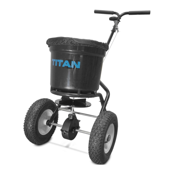
- Page 1 50lb Walk-Behind Spreader OWNER’S MANUAL MPN: 50SPREAD; SKU: 890011 Titan Mfg and Dist, Inc.-3839 Forest Hill-Irene Rd. St#100 Memphis, TN 38125...
- Page 2 1. HELPFUL HINTS: READ THE DIRECTIONS BEFORE ASSEMBLY WHEN ALL ELSE FAILS, READ THE DIRECTIONS AGAIN If your spreader does not spread evenly, be sure the FRONT on the gear box points to the front of the spreader. The impeller must turn clockwise. Reversing the gear box will cause the impeller to turn counter clockwise.
-
Page 3: Assembly Instruction
ASSEMBLY INSTRUCTION Turn Hopper (#16) upside down and attach Frame (#30) using four screws ST6.3 x 40 (#43). 2.a) Slide the Impeller (#42) onto the spindle of the Gear Box Assembly (#39). b) Insert Screw M4 x20 (#41) through the Impeller and the top of the gear box spindle. - Page 4 3.a) Find the two Wheel Assembly Frames (#20). b) Insert M6 x 60 bolt (#32) through the right hand Wheel Assembly Frame (#20) and into the Hopper Frame Assembly (#30). Secure with Lock Nut M6 (#24). Repeat on left side. NOTE: The nuts and bolts do not have to be completely tightened yet.
- Page 5 5.Slip Inner Axle Bushing (#37) onto the right side of the axle, pushing the Inner Axle Bushing into the Outer Axle Bushing until tight. Attach Wheel (#36) to the right side of the axle by inserting a M5 x 45 bolt (#47) and fastening with Lock Nut M5 (#44). Attach Axle End Cap (#35) by tapping with a wooden or rubber mallet.
- Page 6 Insert Bolts M6 x 45 (#11) through the 7. a) Upper Left Handle (#23), then through the Handle Spacer (#1) and Upper Handle on the Right side, screw with Flat Washer Ø 6 (#48) and Lock Nut M6 (#24). Slide Gauge and Lever Assembly (#4) onto the bolts and fasten with Lock Nut M6(#24).
- Page 7 Slip the threaded end of Adjustable Connecting Rod (#46) into the Shut Off Plate (#27) with a Flat Washer Ø6(#48) , then fasten with Flat Washer Ø6(#48)and Lock Nut M6 (#24). a) The three large holes at the bottom of the hopper should match the three holes in the adjustable plate.
- Page 9 DRAWING...
-
Page 10: Parts List
PARTS LIST Ref# Drawing No. Description N570-00012-000 Handle Spacer 9114-06025-DG Carriage Bolt M6x25 9315-08000-DG Teeth Washer Ø8 N570-10000-000 Gauge & Lever Assembly N570-00001-000 Adjust Handle Pole N570-00014-000 Adjust Handle A N570-00015-000 Adjust Handle B 9199-04018-DG Screw ST4.2x18 N510-00016-000 Spacer N510-00019-000 Wing Nut M6 9101-06045-DG Hex Bolt M6x45... - Page 11 Ref# Drawing No. Description N578-01000-000 Gear Box & Axle Assemble N570-00002-000 Thin Washer 9199-04020-DG Screw M4x20 N510-00003-000 Impeller 9199-06040-DG Screw ST6.3X40 9206-05000-DG Lock Nut M5 N570-00021-000 Cross Brace N570-00004-000 Adjust Connect Rod B 9101-05045-DG Hex Bolt M5X45 9301-06000-DG Flat Washer Ø6 N570-00022-000 Rain Cover 9306-06000-DG...
-
Page 12: Using Your Spreader
USING YOUR SPREADER 1. Determine approximate square footage of area to be covered and estimate amount of material required. 2. Before filling the hopper, make sure the flow control arm is in the off position and the closure plate is shut. 3.
Need help?
Do you have a question about the 50SPREAD and is the answer not in the manual?
Questions and answers