
Related Manuals for Beckhoff SCT Series


Summary of Contents for Beckhoff SCT Series
- Page 1 Documentation | EN SCT5xxx Ring-type current transformer for differential current 0...2 A, type B/B+ (all- current sensitive), ISO62020-1 conform 2022-09-29 | Version: 1.0...
-
Page 3: Table Of Contents
Table of contents Table of contents 1 Foreword .............................. 5 Notes on the documentation ...................... 5 Safety instructions .......................... 6 2 Product overview ............................ 8 Introduction ............................ 8 Basics current transformers ...................... 9 Product categories – SCTxxxx current transformer ................ 14 3 Technical data ............................ - Page 4 Table of contents Version: 1.0 SCT5xxx...
-
Page 5: Foreword
, XTS and XPlanar are registered trademarks of and licensed by Beckhoff Automation GmbH. Other designations used in this publication may be trademarks whose use by third parties for their own purposes could violate the rights of the owners. Patent Pending... -
Page 6: Safety Instructions
All the components are supplied in particular hardware and software configurations appropriate for the application. Modifications to hardware or software configurations other than those described in the documentation are not permitted, and nullify the liability of Beckhoff Automation GmbH & Co. KG. Personnel qualification This description is only intended for trained specialists in control, automation and drive engineering who are familiar with the applicable national standards. - Page 7 Foreword • The operating instructions. • The fact that operating instructions can only list general regulations and that these regulations must be followed. • Check the device carefully for transport damage prior to commissioning. The device must not be put into operation if it is mechanically damaged.
-
Page 8: Product Overview
The SCT series portfolio is extremely diversified, ranging from the low-cost 3-phase transformer sets for properties and standard industrial transformers for mechanical engineering, through to solutions for test benches with particularly high requirements for accuracy. -
Page 9: Basics Current Transformers
Product overview Basics current transformers Basic information on the technology area of current transformers is given in the following. The information is of general nature; so it is imperative to check the extent to which these notes apply to your specific application. - Page 10 Product overview Fig. 3: Principle coil current transformer WARNING Dangerous voltages with secondary side not connected The secondary winding must be connected to a current measuring device or short-circuited, otherwise high core losses or dangerous voltages may occur on the secondary side. Before replacing the measuring elec- tronics in the secondary circuit, the current transformer must therefore be short-circuited at its secondary terminals.
- Page 11 Product overview Technical terms of current transformers Term Explanation Primary rated current I (alternative Value of the rated current on the primary side symbol I Secondary rated current I Value of the rated current on the secondary side. Rated power S Value of apparent power (in [VA]) that the transformer can deliver to the secondary circuit at secondary rated current and rated load Rated frequency f...
- Page 12 Product overview Principle of the fluxgate current measurement technology While all SCT transformers except the SCT5xxx are based on the transformer principle described above, the technology of the all-current sensitive differential current transformers is fundamentally different. Fig. 4: Principle fluxgate current measurement technology The measuring principle of the SCT5xxx is based on a differential current measurement of two oppositely excited cores in the transducer.
- Page 13 General description of the fluxgate current measurement technology The SCT series SCT5xxx is used for monitoring differential currents in electrical power supply systems that do not require fast system shutdown. The SCT5xxx type B/B+ can measure DC and AC residual currents at frequencies up to 100 kHz.
-
Page 14: Product Categories - Sctxxxx Current Transformer
Product overview Product categories – SCTxxxx current transformer Breakdown of the type designation of the SCT current transformer Fig. 6: Designation key of the SCT current transformers Version: 1.0 SCT5xxx... - Page 15 Product overview Coil current transformers Fig. 7: SCT0xxx In order to guarantee the power transmission, current transformers need a correspondingly large measuring core volume with decreasing primary nominal currents. The dimensions of standard current transformers would quickly hit their limits on the basis of this physical principle. The SCT0xxx coil current transformers with electrical isolation are specially designed for these low primary nominal currents and are used in corresponding applications.
- Page 16 Product overview Mini ring-type current transformer Fig. 8: SCT1xxx The SCT1111 mini ring-type current transformer can be positioned on a DIN rail by means of snap-on mounting and is thus suitable for measurements in very tight installation spaces, e.g. directly in the sub- distribution unit.
- Page 17 Product overview Ring-type current transformer Fig. 9: SCT2xxx The SCT2xxx series offers a large selection of ring-type current transformers for primary currents from 60 to 2500 A in six sizes and two accuracy classes. The innovative screwless connection technology for rigid and flexible conductors saves time –...
- Page 18 Product overview Ring-type current transformer Accuracy class 1, SCT2111 Primary current 0...60 A AC to 0...500 A AC, Secondary current 1 A AC, Max. diameter round conductor 25.7 mm (size 1) Accuracy class 0.5, SCT2121 Primary current 0...125 A AC to 0...600 A AC, Secondary current 1 A AC, Max. diameter round conductor 25.7 mm (size 1) Accuracy class 1, SCT2211 Primary current 0...600 A AC / 750 A AC,...
- Page 19 Product overview 3-phase ring-type current transformers Fig. 10: SCT3xxx The compact SCT3xxx 3-phase ring-type current transformers for direct mounting below commonly used power switches measure primary currents from 3 x 50 to 3 x 600 A, with secondary currents of 1 or 5 A. The SCT3xxx series is available throughout in accuracy class 1 and is supplemented by the SCT3121-0125 and SCT3121-0150 current transformers in accuracy class 0.5.
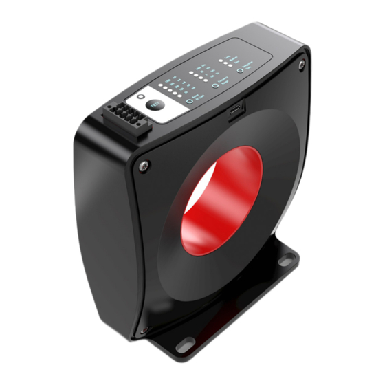
- Page 20 Product overview Ring-type current transformer for differential current measurement Fig. 11: SCT5xxx The increasing prevalence of DC loads (e.g., LED lighting, DC motor drives, 48 V DC bus systems, etc.), distributed DC generation (e.g., PV systems, UPS, batteries, etc.), and high-frequency converters (e.g., SMPS, motor drives, etc.) in industrial environments makes it increasingly difficult to reliably measure insulation faults with conventional current transformers designed for AC 50/60 Hz with limited measurement bandwidth.
- Page 21 Product overview Split-core current transformers Fig. 12: SCT6xxx The separable measuring system of the SCT6xxx split-core current transformers enables flexible retrofitting without disconnecting the primary conductor. Due to the minimal installation effort, they are suitable for use in places that are difficult to access or where space is limited. Four sizes are available. Accuracy class 3 is suitable for primary currents from 60 to 150 A, accuracy class 1 for 200 to 1000 A.
- Page 22 Product overview Busbar split-core current transformers Fig. 13: SCT71xx Like the SCT6xxx series, the SCT7xxx busbar split-core current transformers for primary currents up to 5000 A can be retrofitted to existing systems with no great mounting effort. From 500 A, there is a choice between accuracy class 0.5 and 1 for each primary current.
-
Page 23: Technical Data
Technical data Technical data SCT5xxx | Ring-type current transformer for differential current, size 5 3.1.1 SCT5564 Primary side SCT5564 Rated primary current I 100 A (I = 30 mA) Δn 300 A (I = 100-1000 mA) Δn Rated continuous thermal current I 100 A Δcth Rated short-time thermal current I 200 A (max. - Page 24 Technical data General SCT5564 Supply voltage 24 V dc +10 % / -15 % Permissible ambient temperature range during -20…+55 °C operation Permissible ambient temperature range during -40 … +85 °C storage Permissible relative air humidity 20 … 80 % (no condensation) Protection rating IP20 Connection secondary DFMC 1.5-3.5 2x5way (PN: 1790519), or compatible Conductor cross-section secondary...
- Page 25 Technical data Fig. 15: Side view, front view, all dimensions in mm SCT5xxx Version: 1.0...
-
Page 26: Commissioning
Commissioning Commissioning DANGER Open transformer circuits lead to electric shock and arc flashover! Disregarding this will result in death, physical injury or considerable damage to property! • Never open the secondary circuit of the current transformer under load. • Short-circuit the secondary current terminals of the current transformer before removing the device. WARNING Hazardous voltage can lead to electric shock and burns! •... -
Page 27: Mounting Instructions, Mounting Options
Commissioning Mounting instructions, mounting options • Make sure that the working environment is safe during assembly, maintenance and installation work. Interrupt the power supply of the primary conductor and secure against being switched on again inadvertently. • Install the current transformer on the primary conductor. •... - Page 28 Commissioning Fig. 18: Center conductors Version: 1.0 SCT5xxx...
-
Page 29: Measurement Circuit Example Sct5Xxx
Commissioning Measurement circuit example SCT5xxx Fig. 19: Use in single-phase as well as 3- and 4-pin three-phase systems SCT5xxx Version: 1.0... -
Page 30: Connection
Commissioning Connection Fig. 20: Connection Connection point Description 24 Vdc Relay ground 0 Vdc Relay NC contact 0 Vdc Relay NO contact 0 Vdc External test button, contact 1 Analog 4-20 mA output External test button, contact 2 Version: 1.0 SCT5xxx... -
Page 31: Functional Description Sct5Xx
Commissioning Functional description SCT5xx The Beckhoff SCT5xxx ring-type current transformer for differential current measure the instantaneous real- time value of both DC and AC residual current using the built-in transformer head with integrated balanced flux gate detector. To protect the function and especially the fire protection of the electrical system, the SCT converts the True RMS (TRMS) value of the residual current, which corresponds to the amount of heat dissipated in the insulation. - Page 32 Commissioning Fig. 21: SCT5xxx block diagram Version: 1.0 SCT5xxx...
-
Page 33: Automatic Setup
Commissioning Automatic setup The Beckhoff SCT5xxx are capable of performing automatic setup of the user selectable settings for installations in proper condition taken as baseline. This means that during automatic setup, the SCT5xxx automatically measures the residual currents at the plant site with different frequency ranges and integration time settings and selects the nominal residual current limit that is at least 50% higher than the measured value. -
Page 34: Description Of The User Interface Sct5Xxx
Commissioning Description of the User Interface SCT5xxx The SCT5xxx have three user selectable parameters, for each of which 3-5 different values can be selected. The simple and intuitive user interface is located on the top of the device and is used to configure the transformer with three buttons located below the interface. - Page 35 Commissioning 4. Rated RC limit (RL) The rated RC limit (RL) refers to the measured TRMS value of the residual current that will trip the relay output. Additionally, selecting the three lower trip limits (30-100-300 mA) changes the analog output range to 0 - 0.4 A , while selecting the two upper trip limits (500 - 1000 mA) changes the analog output range to 0 - 2 A...
-
Page 36: Application Example
Fig. 24: Beckhoff SCT5 series An increase in the measured levels with the residual current monitor may indicate a fault in the insulation of the system. - Page 37 Application example system-related leakage currents are mainly capacitive. However, the RCD cannot distinguish between the different leakage currents. Therefore, it can already trip when the sum of all system-related leakage currents is above the tripping threshold. This is also possible during normal operation. Fig. 25: Electrical equivalent circuit diagram of a speed-controlled motor As shown in the figure, different frequency components can occur in the differential current from DC up to several kHz.
-
Page 38: Appendix
Appendix Appendix Documentation issue status Version Comment - First public issue - Corrections complements - Preliminary version Version: 1.0 SCT5xxx... -
Page 39: Support And Service
Please contact your Beckhoff branch office or representative for local support and service on Beckhoff products! The addresses of Beckhoff's branch offices and representatives round the world can be found on her internet pages: https://www.beckhoff.com You will also find further documentation for Beckhoff components there. - Page 41 More Information: www.beckhoff.com/SCT5xxx Beckhoff Automation GmbH & Co. KG Hülshorstweg 20 33415 Verl Germany Phone: +49 5246 9630 info@beckhoff.com www.beckhoff.com...
Need help?
Do you have a question about the SCT Series and is the answer not in the manual?
Questions and answers