Table of Contents
Advertisement
Quick Links
Advertisement
Table of Contents

Related Manuals for SmartHeat bravour BW Series


Summary of Contents for SmartHeat bravour BW Series
- Page 1 >> V2.1.5 Subject to technical changes. Operating & installation instructions bravour & & compact heat pump bravour >> www.SmartHeat.de...
- Page 2 The heat pumps of the SmartHeat product range distinguish themselves by an optimization according to ecological points of view. The increasing performance as well as the use of coolants which are very harmful to the environment are to important criteria which had been taken into consideration when designing the units.
-
Page 3: Table Of Contents
Proper use _____________________________________________________________________________ 4 Product description________________________________________________________________________ 5 Direct expansion - Heat Pump: bravour DI____________________________________________________ 5 Brine-water heat pump: SmartHeat bravour BW(i) _____________________________________________ 5 Water-water heat pump: SmartHeat bravour WW(i) ____________________________________________ 5 Options _________________________________________________________________________________ 7 Option R - Active cooling _________________________________________________________________ 7 Option N- Passive cooling ________________________________________________________________ 8 Option S –... -
Page 4: General Notes
If it is necessary to switch off the complete system during the heating period, there is a risk that the system freezes. In order to avoid damages caused by frost, empty the water circuit of the system after complete switching off or decommis- sioning of the system. >> www.SmartHeat.de... -
Page 5: Basic Instructions
25 … 55°C 5-7K Heating circuit 25 … 65°C 5-7K Heating circuit BWi/WWi 25 … 60°C 5-7K Heat source BW / BW Option i -10 … 15°C 3-5K Heat source WW / WW Option i 5 … 15°C 3-5K >> www.SmartHeat.de... -
Page 6: Product Description
(evaporator) and the energy supply is made available as usable energy by the heat pump. The heat emitting side of the SmartHeat bravour heat pump operates with a heat exchanger as a condenser and, in this way, heats the water for heating and domestic hot water (DHW). - Page 7 < 10 < 10 substances Furthermore, we recommend the installation of a flow meter in the well water circuit by the customer in order to protect the heat pump against non-continuous volume flows and thus against possible damages. >> www.SmartHeat.de...
-
Page 8: Options
If the condensing takes place at the surface or inside of the walls, there is the danger of damages by mildew. Please consider that the room temperatur should not be lower than 6 K below outside air temperature with respect to health! >> www.SmartHeat.de... -
Page 9: Option N- Passive Cooling
A reduction of the cooling capacity during the summer can occur especially in brine water systems, as the ground continues to be heated up. With increas- ing brine temperatures the transferable cooling capacity of the heat exchanger is decreasing. Specification-conform application >> www.SmartHeat.de... - Page 10 A mutual influence of the cooling and hot water preparation will be avoided by this. Further more, the possibility exists to integrate a solar thermal plant to support warming of domestic hot-water. >> www.SmartHeat.de...
-
Page 11: Option S - Solar
The module solar is an optional module for the upgrading of your heat pump device during production at the factory. The indications for the following heat pumps are binding: bravour Serie: DI / BW(i) / WW(i) The operating limits of the respective heat pump please refer to the datasheet >> www.SmartHeat.de... -
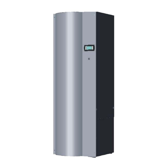
Page 12: Device View
5 Device view Deaerator Operating unit Control unit Tank Inverter Refrigeration module incl. pumps perspective view isometric view open Connection opening domestic water Connection opening hydraulic Connection opening hydraulic Fig.: front view Fig.: side view right Heat sink inlet >> www.SmartHeat.de... - Page 13 >> V2.1.5 Subject to technical changes. Operating & installation instructions bravour Heat sink outlet Source outlet Source inlet Fig.: lower side plate right Fig.: Upper side plate right and left Fig.: rear plate >> www.SmartHeat.de...
-
Page 14: Transportation
The installation space must be dry and frost-free and have a plane and horizontal ground. The ground must be dimen- sioned according to the weight of the SmartHeat bravour heat pump. The connection to the heating and heat source system should be as short as possible. - Page 15 Operating & installation instructions bravour Minimum clearances for the installation Observe the distance to other neighbouring units 25cm (expansion tanks, storages, etc.)! 100cm 100cm 120cm Fig.: Minimum dimensions for the installation of bravour Foundation Fig.: Foundation plan bravour >> www.SmartHeat.de...
-
Page 16: Assembly
The connections for the heat pumps of the bravour series are to lead from the right side or from behind in the ma- chine. Comprehensive hydraulic accessories such as e.g. connection kits, switching units, etc. (refer to product cata- loguet) are available for the optimum connection in the SmartHeat system accessories. -
Page 17: Connection Of The Heating System
After having performed the installation of the heating system, fill, bleed and squeeze off the heating system. For the optimum connection comprehensive hydraulic accessories are available from the SmartHeat system, such as e.g. connection kits, switching units, etc. If inappropriate connection material is used for the hydraulic installation strong noise development, malfunctions or material damages might occur! The integration of the heat pump into the heating network and for drinking water preparation may be very different depending on the respective application. -
Page 18: Connection Of The Domestic Hot Water (Dhw) Tank
Close the circulation connection, if you do not use it. If you set the DHW temperature with 60° or higher, on site a safety protection against scalding has to be installed (e.g. ESBE Serie 30MR). connection M-12 deareator adjustable feet 1/8 inch int. thread >> www.SmartHeat.de... -
Page 19: Electrical Connection
tion of the supply line between the electricity meter, fuses, main switch, motor protective switch and terminal box. Heating engineers authorizes by SmartHeat or correspondingly qualified electricians may perform the electri- bravour cal connection of the heat pump . - Page 20 With water/water and air/water heat pumps, a flow switch must be used. Non-compliance can lead to serious damage in the source area. In such a case, no li- ability claims against SmartHeat may be invoked The outputs are capable of bearing maximum 1.0 A.
-
Page 21: Commissioning
MAG and to set the system pressure as soon as no more air is escaping from the heat circuit. As soon as this is done, the process can be considered as completed and the system will work successfully after de-aerating the system once again, in particular also the reservoir. The rinsing process should be performed and logged according to VDI 2035. >> www.SmartHeat.de... - Page 22 In the frame of the substances are added to the heating water, which let the dissolved alkaline earths precipitate as mud. This mud must be removed from the heating system by system technical and operational measures (desludging). >> www.SmartHeat.de...
-
Page 23: Control
The manual operation must only be used by the specialist for maintenance and service. This manual operation de-commissions all control and safety functions. Please request any further information as well as a commissioning log at the ser- vice hotline: +49 3843 / 2279-111. >> www.SmartHeat.de... -
Page 24: Maintenance, Cleaning And Care Instructions
Any possible errors and their corresponding remedies are listed in the instructions of the controller (refer to part 2 of the operating instructions). If it is not possible to remove a failure by oneself inform an approved installer or service technician. Additional information is available upon request at the service hotline: +49 3843 / 2279-111 >> www.SmartHeat.de... -
Page 25: Screed Heating
Environmentally relevant requirements with regard to recycling, reuse and dispos- al of fuels and components according to the common standards must be complied with. At this it is particularly important to ensure a professional disposal of the coolant and refrigeration oil. >> www.SmartHeat.de... -
Page 26: Hydraulic Examples
A minimum outgoing and backflow temperature of 25°C has to be ensured! 14.2 Hydraulic schematics The following hydraulic schematics do not substitute professional planning. Observe valid rules and legal regulations! All hydraulics and schemata are remarks. >> www.SmartHeat.de... - Page 27 >> V2.1.5 Subject to technical changes. Operating & installation instructions bravour Hydraulic system bravour BW(i) >> www.SmartHeat.de...
- Page 28 >> Operating & installation instructions bravour Subject to technical changes. V 2.1.5 Hydraulic system bravour WW(i) >> www.SmartHeat.de...
- Page 29 >> V2.1.5 Subject to technical changes. Operating & installation instructions bravour Hydraulic system bravour DI >> www.SmartHeat.de...
-
Page 30: Symbole Key
Five-way-brine circuit mainfold S 1.3 Six-way-brine circuit mainfold S 1.4 Safety set source Set natural cooling Safety assembly source Safety set active cooling Safety assembly heating Connection set Circulation-pump-set Heat meter Safety set heating system Drinking water connection set >> www.SmartHeat.de... - Page 31 >> V2.1.5 Subject to technical changes. Operating & installation instructions bravour >> www.SmartHeat.de...
-
Page 32: Appendix
>> Operating & installation instructions bravour Subject to technical changes. V 2.1.5 15 Appendix EU declaration of conformity Technical data Terminal assignment plan >> www.SmartHeat.de... - Page 34 EU Konformitätserklärung/ EU Declaration of conformity Der Unterzeichner/ The signatory: SmartHeat Deutschland GmbH Am Augraben 10 D 18273 Güstrow bestätigt hiermit, dass die nachfolgenden Geräte in der certifies that the following indicated devices introduced von uns in Verkehr gebrachten Ausführungen die...
Need help?
Do you have a question about the bravour BW Series and is the answer not in the manual?
Questions and answers