
Summary of Contents for Technovision TVS-S1
- Page 1 TECHNOVISION ENERGY PVT LTD PUNE S e r v o Voltage Stabilizer User Manual ________________________________________________________________________________________________________________________________...
- Page 2 T E C H N O V I S I O N E N E R Y P V T L T D Servo Voltage Stabilizer User Manual Technovision Energy Pvt Ltd "KONARK” Narhe Industrial Area, Pune - 411 041...
-
Page 3: Table Of Contents
Contents Sr No. Descriptions Page No. Introduction Information for Safety Using this manual Quality and Standard Guarantee Declaration of the management Standard Environment Equipment recycling at the end of its useful life Packaging Presentation Views 4.1.1 Equipment views 4.1.1.1 Single phase Air cooled Stabilizer 4.1.1.2 Three phase Air Cooled Stabilizer 4.1.1.3 Three phase Air cooled Series with Isolation Transformer 4.1.1.4 Three phase Oil cooled Series... -
Page 4: Sr No
Sr No. Descriptions Page No. 5.2.3 Unpacking 5.2.4 Transport till its location 5.2.5 Connections 5.2.6 Input and output wire selections 5.2.7 Connection of input terminals 5.2.8 Connection of output terminals 5.2.9 Connection of the protective earth Operating Controls before commissioning Start up and shutdown of the stabilizer 6.2.1 First commissioning procedure... -
Page 5: Introduction
We thank you for purchasing our SERVO VOLTAGE STABILIZER. From “TECHNOVISION ENERGY PVT LTD” We look forward to a long lasting relationship from hereon. We are pleased to present the Operating Manual for your “TECHNOVISION ENERGY PVT LTD” SERVO VOLTAGE STABILIZER. -
Page 6: Information For Safety
INFORMATION FOR SAFETY 2.1. USING THIS MANUAL The generic information of the equipment is supplied in soft copy on technovision official website, and it includes among other documents the own user's manual of the system and the document concerning to «Safety instructions». - Page 7 When an equipment differs from the one shown in figures, additional annexes will be edited if they were deemed appropriate or necessary. Download on technovision official website. Finally, once the equipment is installed and operative, for future requests or doubts that could arise, it is...
-
Page 8: Quality And Standard Guarantee
Chapter QUALITY AND STANDARD GUARANTEE 3.1 DECLARATION OF THE MANAGEMENT Our target is the client’s satisfaction, therefore this Management has decided to establish a Quality and Environmental policy, by means of installation a Quality and Environmental Management System that becomes us capable to comply the requirements demanded by the standard ISO 9001:2001 and ISO 9001:2015 and by our Clients and concerned parts too. -
Page 9: Environment
Declaration of conformity CE of the product is at the client disposal under previous request to our headquarters offices. 3.3. ENVIRONMENT This product has been designed to respect the Environment and manufactured in accordance with the ISO 14001 norm. 3.4 EQUIPMENT RECYCLING AT THE END OF ITS USEFUL LIFE Our company commits to use the services of authorized societies and according to the regulations, in order to treat the whole recovered product at the end of its useful life (contact your distributor). -
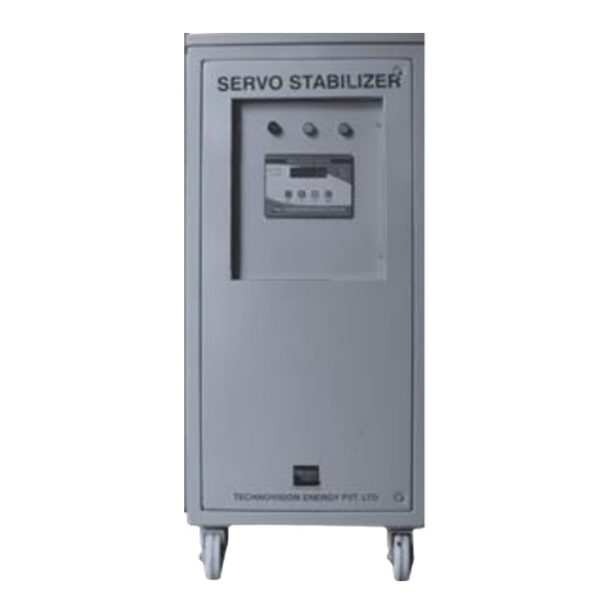
Page 10: Presentation
Single phase Air cooled Stabilizer KVA Rating Voltage Rating Dimensions Model Number (L X W X H) Input Output TVS-S1 1 KVA 170-270 VAC 230 VAC 230 X 305 X 180 TVS-S5 2.5 - 5 KVA 170-270 VAC 230 VAC... -
Page 11: Three Phase Air Cooled Stabilizer
4.1.1.2 Three phase Air Cooled Stabilizer Model Number KVA Rating Voltage Rating Dimensions (L X W X H) Input Output TVS-T10 7.5 - 10 KVA 340 - 480 VAC 415 VAC 400 X 450 X 840 TVS-T15 10 - 15 KVA 340 - 480 VAC 415 VAC 400 X 450 X 840... -
Page 12: Three Phase Air Cooled Power Conditioner Series
4.1.1.5 Three phase Air cooled Power Conditioner Series Model Number KVA Rating Voltage Rating Dimensions (L X W X H) Input Output TVS-TPC15 10 - 15 KVA 360 - 460 VAC 415 VAC 400 X 450 X 840 TVS-TPC30 20 - 30 KVA 360 - 460 VAC 415 VAC 400 X 800 X 850... - Page 13 Any three phase servomotor stabilizer has only one electronic control card for all the phases and one Display card for its monitoring and complete control, less those ones that consist of three independent single phase equipment’s duly connected to make a three phase equipment. In these ones, each cabinet will have its own electronic control card and its display card.
-
Page 14: Main Quality Performances
Although the input voltage range is ±15 % for the standard models, under request, it is possible to manufacture equipment’s with wide input voltage range up to ±30 % (input voltage window). The voltage stabilizer protects against sudden changes, irregularities, increasing or decreasing of the voltage mains by means of an accurate voltage stabilization. -
Page 15: Panel Indication & Controls
4.4 PANEL INDICATION & CONTROLS This indicator shows the input availability Input on This indicator shows the output availability Output on This indicator shows the input high or input low i.e. High/low voltage indicator beyond or below the range of voltage stabilizer. ... -
Page 16: Control System
or subtracting the line voltage is being controlled. A solid state sensor unit continuously monitors the output voltage and the error voltage is compared with fixed reference voltage. The error is amplified through high gain Pic micro contoller18F450 which in turn controls the direction of the motor movement. This drives an Auto Transformer moving arm position till the correct output voltage is restored. -
Page 17: Options
4.6 OPTIONS 4.6.1 Manual Bypass Manual bypass option consists in a two positions cam switch, which allows selecting between positions MAINS «1», where the output is connected to the input of the stabilizer directly (Bypass) and position SERVO «2» where the output of equipment is connected to the output of the stabilizer directly. OFF «0»... -
Page 18: Major Component
MAJOR COMPONENT 4.7.1 VARIAC Variac is also known as Dimmer, Autotransformer or Variable transformer It is normally round in the shape. Silicon CRGO toroidal core is used for the base & copper wire with specific turn ratio according to the capacity is used. The basic purpose of dimmer is to increase or decrease the voltage which is fed to the buck boost transformer. -
Page 19: Servomotor (Synchronizing Motors)
4.7.3 SERVOMOTOR (SYNCHRONIZING MOTORS) Servomotor as the name suggests is the main part of servo stabilizer. The motor rotates the arm connected on the dimmer in clockwise or anti clockwise direction according to input voltage. 4.7.4 CARBON BRUSH This is a moving part in servo stabilizer, it is fitted in the shaft to make the contact with Variac. If the input voltage variation is very frequent, this carbon brush will erase early and customer has to replace it very frequently. -
Page 20: Spd( Surge Protection Device)
4.7.6 SPD( Surge protection device) The Surge Protection Device (SPD) is a component of the electrical installation protection system. This device is connected in parallel on the stabilizer input power supply circuit this is the most commonly used and most efficient type of Electrical Spikes, Sudden Voltage fluctuation protection. 4.7.7 MCB/MCCB The MCB is used to switch on /off the servo stabilizer and gives short circuit protection whereas MCCB is normally for overload protection. -
Page 21: Installation
Chapter INSTALLATION Read and respect the Safety Information, described in section 2 of this document. To obviate some of the indications described in it, can cause serious or very serious injuries to the persons in direct contact or in the vicinity, as well as faults in the equipment and/or loads connected to itself. - Page 22 to select the suitable cross cable section, by respecting the Local and/or National Low Voltage Electro technical Regulations. Regarding the size of the terminals of the built switches in the protection panel, the cross cable section has to be considered, in order to leave them completely embraced in all its section, in order to have an optimal contact between both elements ...
-
Page 23: Equipment Reception
5.2 EQUIPMENT RECEPTION 5.2.1 Unpacking, inspection and contents checking When receiving the equipment, check that no incident has happened during transport (impact, fall ...) and the specifications of the equipment correspond with the ones stated in the order, therefore it is recommended to unpack the stabilizer in order to make a first visual inspection. ... - Page 24 Technovision Service Team Contact details mansion in Annexure of the manual. Compare the components of the shipment with the bill of lading. Report any missing items to the carrier and to Technovision immediately. TIPPING/HEAVY EQUIPMENT HAZARD • The unit is easily tipped. Use extreme caution when unpacking and moving the equipment.
-
Page 25: Transport Till Its Location
5.2.4 Transport till its location Equipment’s in case have four casters, in order to make easier their transport until their location. Nevertheless, if the reception area is far from the installation place, it is recommended to move the equipment by means of pallet jack or the suitable means evaluating the remoteness between both points. -
Page 26: Input And Output Wire Selections
5.2.6 Input and output wire selections Select circuit breaker and cable size as per table Servo Stabilizer Input & Output Cable requirement cha rt Input Operating Range (360-460) VAC Output 415 VAC +/-1% Input Details Input Breaker Output Details Output Breaker 3P+N Current(A) -
Page 27: Connection Of Input Terminals
Servo Stabilizer Input & Output Cable requirement chart Input Operating Range (280-520) VAC Output 415 VAC +/-1% Input Details Input Breaker Output Details Output Breaker 3P+N Current(A) Cable MCB/MCCB (3P) Current(A) Cable (Sqmm) MCB/MCCB (3P) (Sqmm) 16.67 10.87 22.22 14.49 33.33 21.74 44.44... -
Page 28: Connection Of Output Terminals
The illustrations corresponding to models in cabinet are shown with direct connection over the maneuvering mechanism as a mere example. Models with no terminals, the connection order will not differ from the one stated unless the labelling of the equipment states it ... -
Page 29: Connection Of The Protective Earth
affected by the short-circuit only 5.2.9 Connection of the protective earth As this is an equipment with class I protection against electrical shocks, it is essential to install the protection earth conductor (connect earth). Connect this conductor, before supplying voltage to the input terminals. ... -
Page 30: Operating
Chapter OPERATING 6.1 CONTROLS BEFORE COMMISSIONING Make sure that all the connections have been made properly and sufficiently tight, respecting the labelling of the equipment. Check that start up switch of the stabilizer is in «0» or «Off» position. ... -
Page 31: Shutdown Of The Stabilizer
6.2.2 Shutdown of the stabilizer Shutdown the load or loads. Turn to position «0» or «Off» the input circuit breaker of the stabilizer. them this function when they isolators, because they are not built in to break current. ... -
Page 32: Control Panel Overview
Chapter CONTROL PANEL 7. OVERVIEW: 7.1 board connections:... -
Page 33: Wiring Diagram
7.2 wiring diagram: 7.3 TRIAC connections:... -
Page 34: Led Indication
NOTE: - If the motor is running in wrong direction, interchange pin no. 2 & pin no. 3 of the respective phase. 7.4 LED indication: Condition Input Fail Indication Red LED (IP Fail) Phase Reverse Indication Red LED (Ph. Rev) Overload Indication Red LED (Ovl) Output ON... -
Page 35: Advance Option
7.7 Advance options: The card has two modes of setting i.e. GENERAL SETTINGS: 7.7.1 General settings:- To enter GENERAL SETTINGS long press the ENTER key, user interface will ask for a 4-digit password. Each digit must be set using START/STOP keys and confirmed using ENTER key. Only upon entering a right password can the settings be accessed. -
Page 36: Change User Password
ENTER key to save current value & go to next parameter. To return on GENERAL SETTINGS screen at any moment press the BACK key. For returning to the RUN mode from the GENERAL SETTINGS screen press the BACK key again. P a rameter D e s c r ip t io n R a n g e s... -
Page 37: Motor Test
7.7.6 Motor test: To check motor functioning it can be controlled manually using this setting. The servo motors can be rotated Clockwise & Anticlockwise by pressing the START/STOP keys. Please note that output is turned OFF once user enters into this mode and is turned back ON again when the user comes out of this mode and the output is adjusted by the algorithm 7.7.7 Calibration: For calibrations select CAL option, take pre-calibrated measuring instruments, for Voltage calibration ensure... - Page 38 Upon selecting the calibration option, display will show the parameters given in TABLE , to increment/decrement values use START/STOP key, long press to the START/STOP increment/decrement values rapidly. Press the ENTER key to save current value & go to next parameter. To return on GENERAL SETTINGS screen at any moment press the BACK key.
-
Page 39: Error Indications
7.7.8 Error indications: Condition LCD Indication LED Indication Buzzer Indication Input High I/P Fail (ON), OP (OFF) ON as soon as voltage becomes high & OFF when the voltage becomes normal Input Low I/P Fail (ON), OP (OFF) ON as soon as voltage becomes low &... -
Page 40: Maintenance
Chapter MAINTENANCE 8.1 ANNUAL MAINTENANCE 8.1.1 General. Blow out the dust accumulated on SERVO with heavy duty blower once in month regularly. Check the transmission system of the Variac is still aligned. Correct if it is needed. Check that the movement of the Variac is uniform (no vibrations and no steps). Probably, it is required the replacement of the motor or gear system. -
Page 41: Brushes
8.1.2 Brushes Check the free move of the brushes. Probably, it is required the replacement of the brush. Check the contact surface is smooth. Probably, it is required the replacement of the Variac. Check the pressure over the winding through the spring is correct. Probably, it is required the replacement of the brush spring. -
Page 42: Troubleshooting
Chapter TROUBLESHOOTING S.NO. NOTICED PROBABLE CAUSE REMEDY PROBLEM a) MCB faulty Replace the MCB b) One of the phase Replace the control card output one of the phase output or lower than set value Power fault Output Electronic card. c) Faulty cut-off relay Replace the Faulty relay d) Fused control Replace the blow off fuse. - Page 43 c) Faulty Electronic card c) Replace the faulty card. S.NO. NOTICED PROBABLE CAUSE REMEDY PROBLEM a) Due to faulty servomotor a) Replace the servomotor. Heavy sound b) Due to mechanical b) Check the pinion gear and coupling observed All the misalignment stucked Auto gear, if faulty replace and realign.
- Page 44 S.NO. NOTICED PROBABLE CAUSE REMEDY PROBLEM Output High a) Faulty R-C network a) Replace the R-C network /Output Low b) Faulty Control Card b) Replace the control card c) Fault in motor c) Replace the motor Garbage Value Contactor Coil Voltage Restart the stabilizer through mains shown in display...
-
Page 45: Annexure
Technovision Energy Pvt Ltd KONARK” Narhe Industrial Area, Pune - 411 041 " Phone- 20 24390 063/093/841 / sales@technovisionenergy.com The Technical Service & Support (T.S.S.) network, Commercial network and warranty information are available In Website: www. technovisionenergy.com Service coordinator - 020-24390093 / 09370132704...
Need help?
Do you have a question about the TVS-S1 and is the answer not in the manual?
Questions and answers