Advertisement
Quick Links
Advertisement

Related Manuals for Sermatec SMT-10KTL-TH


Summary of Contents for Sermatec SMT-10KTL-TH
- Page 1 Basic Introduction to Hybrid Inverter SMT-10K- TL-TH...
- Page 2 Product Description Composing PV, Battery, Load and Grid together to realize high efficient storage solution for household rooftop users. Could be set to 6kW, 8kW, 10kW. 2021/8/19 www.sermatec-ess.com...
- Page 3 CONTENT • Product Description • Inverter Overview • System Diagram • Technical Parameters • Installation • Working Modes • • Warranty Maintenance 2021/8/19 www.sermatec-ess.com...
- Page 4 1. PV Connector 2. PV Switch 3. Battery Connector 4. GPRS Module Interface 5. WiFi Antenna Interface 6. Communication Interface 7. Waterproof Vent Valve 8. AC Back-up Load Connector 9. PE Connection Point 10.AC Grid Connector 11.Indicator LED 2021/8/19 www.sermatec-ess.com...
- Page 5 Technical Parameters 2021/8/19 www.sermatec-ess.com...
- Page 6 Technical Parameters 2021/8/19 www.sermatec-ess.com...
- Page 7 Do not operate or maintain the inside of the system during thunderstorms or wet weather to prevent electric shock. If operating inside the Hybrid Inverter, make sure the system is not powered on. 2021/8/19 www.sermatec-ess.com...
- Page 8 Installation Unpacking inspection Unpack the package, review the check list. 2021/8/19 www.sermatec-ess.com...
- Page 9 2. Screwdriver (Philips screwdriver: M3、M6; Flat head screwdriver: M3) 3. Wire stripper(4~6mm² ) 4. Wire crimper 1 (Model: H4TC0001; Manufacturer: Amphenol) 5. Wire crimper 2( OT terminal, 4~6 mm² ) 6. Open-end wrench (Model: H4TW0001; manufacturer: Amphenol) 7. Multimeter 2021/8/19 www.sermatec-ess.com...
- Page 10 3) Ensure installation wall is solid enough to meet the requirements of load bearing for hybrid inverter. 4) The mounting position is supposed to avoid direct sunlight. 2. Installation space requirements Product installation position, leave 300 mm of space for maintenance and heat dissipation left, right and front 2021/8/19 www.sermatec-ess.com...
- Page 11 1.Mark mounting hole on the wall Drill hole with 8mm diameter of bit. Ensure a depth of 80mm. 2.Hammer expansion tube into the wall Mount bracket on the wall, keep aligned with the holes. bracket. 3.Mount the Sermatec hybrid inverter on the 2021/8/19 www.sermatec-ess.com...
- Page 12 Installation 4.Secure the inverters with M6 screw on the right side. 5.Install anti-theft lock if necessary ( Option, equipped by user). 2021/8/19 www.sermatec-ess.com...
- Page 13 2. PV2 Connector Diagram 3. PV Switch 4. Battery Connector 5. GPRS Module Interface 6. WiFi Antenna Interface 7. DRED Interface 8. Communication Interface 9. Waterproof Vent Valve 10.AC Back-up Load Connector 11.PE Connection Point 12.AC Grid Connector 2021/8/19 www.sermatec-ess.com...
- Page 14 Installation 2021/8/19 www.sermatec-ess.com...
- Page 15 The minimum insulation resistance to ground of PV panels must exceed 40k, there is a risk of shock hazard if the requirement of minimum resistance is not met. The recommended connected panels is to exceed 10%-20% of standard number 2021/8/19 www.sermatec-ess.com...
- Page 16 STEP 2: Follow the requirement to cramp and connect H4 connector to cable which you can find from installation kits.Crimp the H4 connector to the cable as required. STEP 3: Use multimeter to measure PV side voltage and verify ,correct polarity, ensure open-circuit voltage is less than 1000V. 2021/8/19 www.sermatec-ess.com...
- Page 17 Suggestion: Batteries must be installed with a distance to each other, details please refer to battery manufacture’s user manual. As for the number of cells used, it will be decided by customer’s choice, the choice must comply with the followed requirement: the voltage is 200-800V. 2021/8/19 www.sermatec-ess.com...
- Page 18 Crimp the H4 connector to the cable as required Battery cable size: 6mm² STEP 2: Use multimeter to measure Battery side voltage and verify correct polarity, ensure open-circuit voltage is less than 800V. STEP 3: Connect positive and negative terminals to the corresponding interfaces. 2021/8/19 www.sermatec-ess.com...
- Page 19 Installation 2021/8/19 www.sermatec-ess.com...
- Page 20 Installation 2021/8/19 www.sermatec-ess.com...
- Page 21 Cable OD 16-20mm, pry inner ring out of connector. STEP 2: The connector and cable are required to be reliably connected as shown below. Order of connection is 1-A(Yellow), 2-B(Green), 3- C(Red), 4-N(Blue) ,-PE Cable sectional area 6 mm², stripping length 10±0.5mm 2021/8/19 www.sermatec-ess.com...
- Page 22 STEP 4: Connect connector to AC Load interface and grid interface , rotate and lock them. Note: Do not connect reverse the backup connector and the grid side connector. STEP 5: Clamp screw assembly STEP 6: PE Installation 2021/8/19 www.sermatec-ess.com...
- Page 23 Installation Notes 1.Back-up side could not be connected with grid directly 2.Back-up side could not be connected with any AC generator 2021/8/19 www.sermatec-ess.com...
- Page 24 Installation Notes 3.Switch specifications of AC side: The air switch usually chooses 1.2-1.5 times of maximum input/output current; Leakage circuit breaker of household usually chooses 30-100mA,and industrial project usually chooses above 300mA. 2021/8/19 www.sermatec-ess.com...
- Page 25 Installation Notes 4.Wiring diagram of 10K 2021/8/19 www.sermatec-ess.com...
- Page 26 5.Off-grid operating conditions have strict requirements on the connected load. The inductive load cannot exceed 1/3 of the maximum operating power of the inverter. 6.One smart meter could not be connected with multiple inverters; one communication cable could not be connected with multiple CTs. 2021/8/19 www.sermatec-ess.com...
- Page 27 Fix firmly by screw. STEP 4: Screw up water-proof cylinder, connect the cable from “RS485” interface to the interface of Power Meter, connect the cable from “To battery” interface to BMS interface in battery ( default length of cable is 3m) 2021/8/19 www.sermatec-ess.com...
- Page 28 The RJ45 socket pin assignments for DRED, Power Meter and BMS as follows: The inverter shall detect and initiate a response to all supported demand response commands, demand response modes are described as follows: 2021/8/19 www.sermatec-ess.com...
- Page 29 Installation There are only two choices for Smart Meter for 10K inverter: Acrel Three Phase( ACR10R- D10TE4/C45), Eastron Three Phase(SDM630MCT V2) 2021/8/19 www.sermatec-ess.com...
- Page 30 3.7 GPRS Module (Optional) and Wi- Fi Antenna Connection If the user selects the GPRS module, remove the dust cover plate of the GPRS module interface and install the GPRS module. Install the antenna to the antenna interface 2021/8/19 www.sermatec-ess.com...
- Page 31 Installation Installation check After the Hybrid Inverter is installed, be sure to check the installation according to the following table! 2021/8/19 www.sermatec-ess.com...
- Page 32 Start Up: Close air switch of grid side--Turn on DC rotary switch-- Turn on the breaker of battery--Startup the system through Sermatec Mate APP. Power off: Shut down the system through Sermatec Mate APP—Turn off the breaker of battery--Turn off DC rotary switch-- Open air switch of grid side.
- Page 33 Working Modes Four Working Modes: 1. General Mode 2. Energy-Storage Mode 3. Micro-Grid Mode 4. Peak and Bottom Mode 2021/8/19 www.sermatec-ess.com...
- Page 34 2. Energy Storage Mode: Suitable for Areas with Unstable Grid PV and Grid supplies power to the Load and charge the Battery. When the Grid is normal, the SOC of Battery keeps 100%. Battery discharges only when Grid is abnormal. Anti-back flow defaults to prohibited 2021/8/19 www.sermatec-ess.com...
- Page 35 During flat period, PV supplies power in the sequence of Load→Battery →Grid. During peak and tip period, PV, Battery and Grid supplies power to Load, and Battery never charges. The surplus power will be sold to the Grid. 2021/8/19 www.sermatec-ess.com...
- Page 36 2. It is required to implement power down before system clean, confirming reliability of electrical connection, ground connection , etc. STEPS to power down Sequentially disconnect ①PV side switch, ②battery side switch, ③PV rotatory switch on the inverter, ④AC grid side switch ⑤ AC load side switch 2021/8/19 www.sermatec-ess.com...
- Page 37 Maintenance Routine Maintenance 2021/8/19 www.sermatec-ess.com...
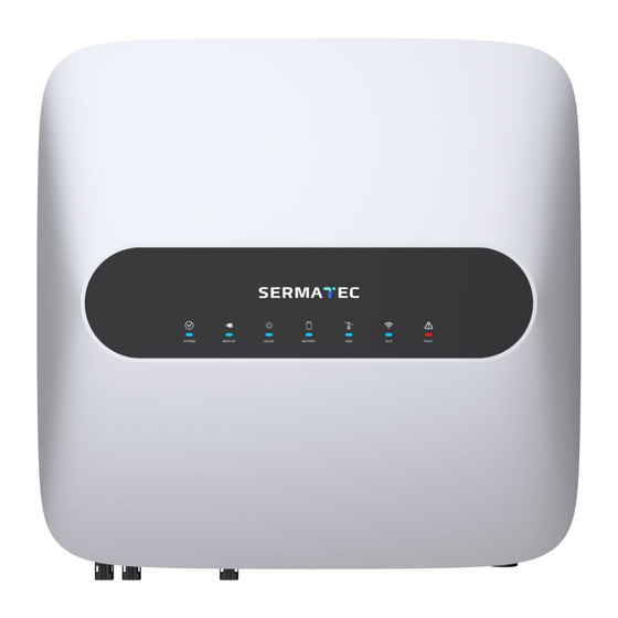
- Page 38 Maintenance LED Status 2021/8/19 www.sermatec-ess.com...
- Page 39 Maintenance Trouble Shooting 2021/8/19 www.sermatec-ess.com...
- Page 40 Maintenance Trouble Shooting 2021/8/19 www.sermatec-ess.com...
- Page 41 Warranty 5 Years Warranty Calculated 6 months after out from factory or installation date which comes the first. The Replacement with be sent together with dealer’s next order,suggest that dealer keeps backup ones in stock. 2021/8/19 www.sermatec-ess.com...
- Page 42 Intentional destruction or defilement, make indelible marks, theft, etc. Normal wear. Unless a special agreement between Sermatec and Lithium battery suppliers, for all the battery packs not listed in ‘Approved battery options statement of Sermatec’ (which could be accessed on Sermatec’s website www.sermatec- ess.com) are not allowed to use on Sermatec’s residential inverters, issues caused by an incompatible battery is not...
- Page 43 Thanks...
Need help?
Do you have a question about the SMT-10KTL-TH and is the answer not in the manual?
Questions and answers