Table of Contents
Advertisement
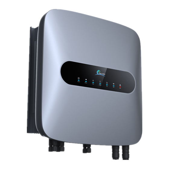
10kW All-in-one Hybrid Inverter User Manual
Important Notice
In order to protect the legitimate rights and interests of users, please read our operating procedures and
safety instructions carefully before using this equipment. Please operate the equipment according to the
operating procedures and safety instructions.
Once using this device, you are deemed to have read, understood, endorsed, and accepted all terms
and contents of the device's operating procedures and safety instructions. The User is committed to
being responsible for his or her actions and all consequences arising therefrom.
The User undertakes to use the device solely for legitimate purposes and agrees to these Terms and
any relevant national policies or guidelines.
In using this equipment, please strictly observe and implement the requirements, including but not
limited to the operating procedures and safety instructions. All personal injury, accident, property
damage, legal disputes, and other adverse events that cause conflicts of interest caused by violations of
the user instructions or force majeure indicated by the safety instructions are the responsibility and loss
of the User. Our company will not assume any responsibility.
Copyright, all rights reserved. The content is subject to change without notice.
Caution!
Failure to observe a warning indicated in this manual may result in injury.
The danger of high voltage and electric shock!
Refer to the operating instructions
Signals danger due to electrical shock and indicates the time (5 minutes) to
allow after the inverter has been turned off and disconnected to ensure
safety in any installation operation.
The danger of hot surface!
Protective earth
Advertisement
Table of Contents

Related Manuals for Sermatec SMT-10K-TL-TH


Summary of Contents for Sermatec SMT-10K-TL-TH
- Page 1 10kW All-in-one Hybrid Inverter User Manual Important Notice In order to protect the legitimate rights and interests of users, please read our operating procedures and safety instructions carefully before using this equipment. Please operate the equipment according to the operating procedures and safety instructions. Once using this device, you are deemed to have read, understood, endorsed, and accepted all terms and contents of the device's operating procedures and safety instructions.
- Page 2 Installation Risk Notification Wear protective gloves when handling equipment by hand to prevent cuts from sharp objects. Warning Make sure the cable label is correct before connecting the cable. Attention Construction operation of high-voltage lines may cause fire or electric shock. The area through which the AC cable is Dangerous connected and routed must comply with local regulations and specifications.
- Page 3 Equipment operation and maintenance must comply with electrical safety operating procedures. Otherwise, there is a risk of fire and electric shock. The personnel responsible for the operation and maintenance of this product must have the qualifications of high voltage and alternating current, etc., He must undergo strict training, master the correct operation method of the system and various safety precautions, and then carry out various equipment operations;...
- Page 4 Modification record The Document version A00 (2019.03.04) The First release The Document version A01 (2019.05.07) 1.2 Modify Working Mode 2.3.2 Add electrical connection diagram 3.1 Update pictures of APP 3.6.2 Note about Battery Lower Limit SOC 4.2 Add Software upgrade 5.3 Update Trouble Shooting The Document version A02 (2019.08.20)...
-
Page 5: Table Of Contents
1.2 Compose and Operating Principle................1 2 Installation..........................8 2.1 Safety regulations......................8 2.2 Installation preparation....................8 2.3 Installation........................12 2.4 Installation check......................23 3 Sermatec APP........................23 3.1 Software acquisition....................23 3.2 Connect to internal Wi-Fi...................23 4 Parallel connecting......................24 4.1 Battery connection...................... 24 4.2 Smart meter......................... 25 4.3 Parallel wiring...................... -
Page 7: The Description Of The Model
This chapter describes the model, composition and configuration, and working principle of the Hybrid Inverter. 1.1 The description of the model Take 10kW inverter for example for model description. Hybrid Inverter model: SMT-10K-TL-TH The model description is shown as below: Three phases Transformer less... - Page 8 The schematic diagram of the primary circuit of the Hybrid Inverter is as follows: Figure1-2 The Hybrid Inverter principle topology Work Modes: Five working modes: General mode, Energy Storage mode, Micro-grid model, Peak-Bottom mode, and AC coupling mode. The Inverter must be configured in APP before startup : working parameters (Grid standard, DC side battery type, battery protocol, meter protocol.), working mode (working mode, utility power price, period setting), and other parameters if neccessary.
- Page 9 Mode 1: General mode (Default) Suitable for Areas with Stable Grid 1. If PV power is sufficient, PV power will supply to the load, then charge the battery, feeding into grid at last if still surplus power (Anti-backflow is forbidden). (Figure1-5) 2.
- Page 10 Figure1-8 Grid is abnormal Mode 3: Micro-grid mode Suitable for Areas without Grid 1. The Micro-grid power source comes from PV, battery. 2. If PV is sufficient, PV power priority supply to the load, then charge the battery. (Figure1-10) 3. When PV is insufficient, Batteries supply power to the load. (Figure1-11) Typical application scenarios: Figure1-9 Sunny day Figure1-10 Night...
- Page 11 Figure1-11 Grid price In Bottom Time Period: Figure1-12 In Flat Time Period: Figure1-13 PV is insufficient Figure1-14 PV is sufficient. In Tip and Peak Time Period: Figure1-15 PV is insufficient Figure1-16 PV is sufficient...
- Page 12 CT self-checking(meter detection) failed. Meter/CT here only communicates with hybrid inverter, so if you enable anti-backflow it works for hybrid inverter only, cannot work on grid-tied inverter as Sermatec inverter cannot control the grid- tied inverter.
- Page 13 Figure 1-17 AC Coupling System Diagram...
-
Page 14: Installation
2 Installation This chapter describes the installation and wiring of the Hybrid Inverter. Please strictly follow the instructions in this chapter to install and wire connection. 2.1 Safety regulations The Hybrid Inverter has high voltage and large current inside. To ensure personal safety, the following regulations should be noted at all times. - Page 15 Figure 2-1 Packing list 2.2.2 The Hybrid Inverter Overview 1. PV Connector 2. PV Switch 3. Battery connector 4. GPRS Module Interface 5. WIFI Antenna Interface 6. Communication Interface 7. Waterproof vent valve 8. AC Backup Load Connector 9. PE connection Point 10.
- Page 16 2.2.3 Cable and Air switch preparation Table 2-1 Wiring and cable requirements table Serial Cable Name Recommended cross-sectional Color of cable Cable model area(mm²) OD(mm) Red, Black 4~6 ø4.5~ PV side DC positive PV1-F ø7.8 and negative input Red, Black ø4.5~...
- Page 17 2.2.5 Installation requirements 1. Wall bracket Installation 1) It is necessary to ensure that the installation position is flat and the thickness of the whole wall exceeds 100mm; 2) Ensure the installation wall is vertical to the ground. If it is sloping, the tilt angle is only allowed to be less than 15°...
-
Page 18: Installation
2.3 Installation 2.3.1 Mounting STEP 1: Mark mounting hole on the wall, drill hole with 8mm diameter of the bit. Ensure a depth of 80mm. Figure 2-5 STEP 2: Hammer expansion tube into the wall mount bracket on the wall, keep aligned with the holes. - Page 19 STEP 4: Secure the inverter with M6 screw on the right side. Figure 2-8 STEP 5: Install anti-theft lock if necessary (Optional, equipped by user). Figure 2-9 2.3.2 Electrical Connection Hybrid Inverter System Connection Diagram Figure 2-10...
- Page 20 For AU/EN Figure 2-11 For Other Countries Figure 2-12...
- Page 21 Dangerous 1) Make sure all switches are at the closed(disconnect) position before the electrical connection. 2 ) Only qualified installation person can implement the installation of AC and DC input cable. 2.3.2.1 Connect PV cable Attention It is strictly prohibited to connect positive poles (PV1+, PV2+, BAT+) and negative (PV1-, PV2-, BAT-) reversely or incorrectly.
- Page 22 PV cable size: 4~6 mm² Figure 2-14 STEP 3: Use multimeter to measure PV side voltage and verify correct polarity, ensure the open- circuit voltage is less than 1000V. Figure 2-15 PV Polarity check 2.3.2.2 Connect BAT cable Attention Make sure that the installation location meets the following conditions: The area is completely waterproof.
- Page 23 used, it will be decided by the customer; the choice must comply with the followed requirement: the voltage is 200-800V. Step 1: Crimp the H4 connector to the cable as required Battery cable size: 6mm² Figure 2-16 STEP 2: Use multimeter to measure Battery side voltage and verify correct polarity, ensure open-circuit voltage is less than 800V.
- Page 24 Figure 2-18 STEP 2: The AC Grid Connector and cable are required to be reliably connected, as shown below. Order of connection is 1-A(Yellow),2-B(Green),3-C(Red),4-N(Blue), Cable sectional area 6 mm², stripping length 12±0.5mm. Figure 2-19 STEP 3: Measure grid voltage by multimeter, ensure grid voltage is less than the high limit of voltage required by all national grid standards.
- Page 25 Dangerous Note: When AC backup LOAD or AC GRID is not in use, please tighten the connector cover. Otherwise there will be electric shock danger, and the IP rating of the inverter will be reduced. STEP 4: Connect connector to AC backup Load interface and grid interface, rotate, and lock them. Figure 2-20 STEP 5: Clamp screw assembly Figure 2-21...
- Page 26 Figure 2-22 2.3.2.4 Communication cable connection STEP 1: Remove the waterproof cover plate that comes with the Hybrid Inverter STEP 2: Plug the wire connector of the waterproof cover plate in the accessory into the corresponding interface of the Hybrid Inverter. STEP 3: Fix firmly by screw.
- Page 27 DRED, Power Meter, and BMS Connection: Figure 2-24 The RJ45 socket pin assignments for DRED, Power Meter, and BMS as follows: Figure 2-25...
- Page 28 If you need to use the DRED function, please put the left dip switch in the upper position. Figure 2-26 The inverter shall detect and initiate a response to all supported demand response commands; demand response modes are described as follows: Table 2-4 Mode Requirement...
-
Page 29: Installation Check
Figure 2-27 The GPRS socket pin assignments as follows: Signal Name 485A 485B Figure 2-28 Install the antenna to the antenna interface. Figure 2-29 Wi-Fi antenna diagram 2.4 Installation check After the Hybrid Inverter is installed, be sure to check the installation according to the following table! Table 2-5 Installation checking list Check content... - Page 30 Check whether the reserved distance below the Hybrid Inverter meets the requirements. Check whether the accessories are complete and the cable is intact and not damaged. Check PV cable polarity, ensure they are connected properly. Ensure PV rotating switch is at OFF position. Check load connector, grid connector whether they are connected properly.
-
Page 31: Sermatec App
3 Sermatec APP Sermatec App is used to check and control inverter parameters. There are two modes: Local Connection Mode and Web Cloud Mode. Local Connection Mode: Use the phone to connect to device by WiFi locally, you can check and set device parameters. -
Page 32: Parallel Connecting
4 Parallel connecting 4.1 Battery connection According to the application scenarios, there are two methods to connect battery to the Hybrid Parallel System(HPS): Battery Independence System(BIS) and Battery Shared System(BSS). In the BIS, every Hybrid inverter connect to its own battery and works independently, as the Figure4-1 shows. -
Page 33: Smart Meter
Figure 4-2 BSS Figure 4-3 SMT-PB10K 4.2 Smart meter The communication wire of the smart meter must connect to the host inverter of the HPS, as Figure 4-1 and Figure 4-2 shows. -
Page 34: Parallel Wiring
4.3 Parallel wiring Each inverter has one parallel communication port, so if the HPS used more than two inverters, a network cable adapter (As the Figure 4-4 shows, which is a accessory of the inverter) is used to connect the Parallel wires together, as Figure 4-1 and Figure 4-2 shows. In addition, a CAN matching resistance(As the Figure 4-5 shows, which is a accessory of the inverter)should be connected to one of the network cable adapters, or sometimes communication may fail. -
Page 35: App Setting
4.7 APP settings After opening Sermatec Mate APP, click “ ” setting menu button, go to “Advanced setting”, then find “Parallel configuration” sub-items, as Figure4-6 shows. Figure 4-6 Parallel Configuration Battery Wiring Type for Parallel Mode Please according to the actual application to choose “Share Battery” or ”Independent Battery”. - Page 36 Figure 4-7 Battery Wiring Type Symbol for Stand-Alone or Parallel Setting It is important to select “Parallel Connection” here, as Figure 4-8 shows, to let the inverter work in a HPS. Figure 4-8 Parallel Connection Setting Device address in parallel mode A HPS needs one inverter to be host and other slavers, as Figure 4-9 shows.
-
Page 37: Parallel Parameter Display
in parallel mode” is set “Host Device”for host inverter in HPS and ”Slaver Device 1/2/3”for other inverters. The slavers address can not be duplicated in the HPS. Figure 4-9 Parallel Address Note: The host inverter must connect to BMS in BSS. The slavers address can not be duplicated. - Page 38 output port voltage and current. In the BIS, the working logic of inverters in HPS are independence, so sometimes, the inverters working status are inconsistent. For example, one inverter’s battery is charging but the other is in idle, or the total power of PV and Grid does not equal to backup load consumed (Because the power can flow between the inverters ).
-
Page 39: Product Maintenance
5 Product Maintenance This Chapter mainly introduces routine maintenance, trouble shooting. Dangerous You will be obliged to implement product maintenance complying with the safe regulations. The personnel to implement internal operation of inverters must be trained and qualified with sufficient knowledge of electrical system. It is required to implement powering down before system clean, confirming... -
Page 40: Routine Maintenance
5.1 Routine Maintenance Table 5-1 Checking Checking Method Maintenance Content Period System Clean Periodic inspection for cooling fan, clean out dust Once in six months to one year System running 1. Observe the physical appearance of the inverter status to determine whether it is damaged or deformed. 2. -
Page 41: Led Status
5.2 LED Status Table 5-2 Display item Status Corresponding state description On:System is active and on-grid SYSTEM Blink:System is active and off-grid Off:System is standby On:AC-Load is active and normal BACK-UP Blink:AC-Load is active and overload Off:AC-Load is off On:All PV is normal SOLAR Blink:One PV is abnormal Off:All PV is abnormal... -
Page 42: Trouble Shooting
Grid Phase Lock Failure 2. If step 1 does not help, please grid contact Sermatec Service team. 1. Shut down inverter and check the AC backup or AC circuit, restart after correction. Grid port have short AC Output Short Circuit Error 2. - Page 43 If it code voltage range still cannot self-recover, please contact the Sermatec service team. 1. Check grid frequency, and restart The frequency of the the inverter after the grid frequency grid is lower than recover to normal range.
- Page 44 Inverter Damage Bus Software Start Up Failure when the power grid is normal. If it still cannot self-recover, please contact the Sermatec service team. Bus Hardware Start Up Failure Inverter Damage 1. Occasional failures can...
- Page 45 Low Battery SOC when PV or grid is normal. Lower Limit Error 3. increase the discharge SOC lower limit setting in Sermatec Mate APP. 4. If above steps cannot help please contact the Sermatec service team. Battery Charge/Discharge Battery current is 1.Occasional failures can...
- Page 46 2.Reduce the load. 3.Change the battery. 4.Reduce the charge or discharge current in Sermatec Mate APP. 5.If above steps cannot help please contact the Sermatec service team. BMS send wrong 1.Shutdown Battery system and fault power on again. 2.Change the battery.
- Page 47 SOC to normal range. 2. If step 1 does not help,please contact the Sermatec service team. 1. Make sure the insulation impedance of the PV module is Insulation PV+ Insulation Impedance greater than 34kΩ. impedance is less Fault 2.
- Page 48 2. The inverter cannot automatically failure recover, shut down, and turn on. If it still cannot self-recover, please contact the Sermatec service team. There are something Check if there are anything around around affecting that affects heat dissipation, if yes, heat dissipation.
- Page 49 The mobile phone is connect to the inverter WiFi. too far from the 2. If step 1 does not help, please inverter contact the Sermatec service team. The grid phase 1. Check and correct the grid phase sequence is wrong sequence.
- Page 50 2. The inverter cannot automatically recover, shut down, and turn on. If it still cannot self-recover, please contact the Sermatec service team. Inverter hardware 1. Occasional failures can error automatically recover. 2. The inverter cannot automatically recover, shut down, and turn on. If it still cannot self-recover, please contact the Sermatec service team.
- Page 51 2. The inverter cannot automatically recover, shut down, and turn on. If it still cannot self-recover, please contact the Sermatec service team. Battery SOC changes 1.Please change work mode to a lot suddenly ‘energy storage’ mode, to charge...
- Page 52 BMS cable must be correctly plugged and the wires should be ok,can measure by multimeter. If everything above is normal, please contact the Sermatec service team. Do not feed 1. Check Working Mode, check PV electricity to the grid power, check load power, check if...
-
Page 53: Technical Parameters
6 Technical Parameters Table 6-1 Technical parameters Parameters PV Input (DC) Maximum PV array power(W) 13000 Vmax PV (V) 1000 Rated voltage (V) Maximum input current(A) 11/11 Isc PV(A) 14/14 MPPT voltage range(V) 200-800 Number of MPPT trackers Max. inverter back-feed current array(A) - Page 54 Grid rated current (A) 14.5 Grid maximum current (A) 16.7 Power factor range 0.8cap...0.8ind Total harmonic distortion (THD, rated power) <3% Parallel operation Load Output (With Battery) Rated power (VA) 10000 Rated voltage (V) 400/380 Electrical connection 3/N/PE Rated frequency (Hz) 50/60 Rated current (A)...
- Page 55 EN61000-6-1/EN61000-6-2/EN61000-6- 3/ EN61000-6-4/ IEC 62920 EN50549-1:2019/AS/NZS 4777.2/ Certification DIN VDE0124-100:2020 Environment limit Ingress protection (IP) rating IP 65 Protective class class I Operating temperature range -25°C...+60°C (>+45°C, derating) Altitude (M) <2000 Storage temperature range -25°C...+60°C Noise emission (dB) <30 DCⅡ; ACⅢ Overvoltage category Dimensions and Weight 548(W)*550(H)*188(D)
Need help?
Do you have a question about the SMT-10K-TL-TH and is the answer not in the manual?
Questions and answers