Table of Contents
Advertisement
5kW All-in-one the Hybrid Inverter User Manual
Important Notice
In order to protect the legitimate rights and interests of users, please read our operating procedures and
safety instructions carefully before using this equipment. Please operate the equipment according to the
operating procedures and safety instructions.
Once using this device, you are deemed to have read, understood, endorsed and accepted all terms and
contents of the device's operating procedures and safety instructions. The User is committed to being
responsible for his or her actions and all consequences arising therefrom.
The User undertakes to use the device solely for legitimate purposes and agrees to these Terms and any
relevant national policies or guidelines.
In using this equipment, please strictly observe and implement the requirements including but not limited to
the operating procedures and safety instructions. All personal injury, accident, property damage, legal
disputes and other adverse events that cause conflicts of interest caused by violations of the user instructions
or force majeure indicated by the safety instructions are the responsibility and loss of the User. Our company
will not assume any responsibility.
Copyright, all rights reserved. The content is subject to change without notice.
Caution!
Failure to observe a warning indicated in this manual may result in injury.
The danger of high voltage and electric shock!
Refer to the operating instructions
Signals danger due to electrical shock and indicates the time(5 minutes)to
allow after the inverter has been turned off and disconnected to ensure safety
in any installation operation.
The danger of hot surface!
Protective earth
Advertisement
Table of Contents

Related Manuals for Sermatec SMT-5K-TL-LV


Summary of Contents for Sermatec SMT-5K-TL-LV
- Page 1 5kW All-in-one the Hybrid Inverter User Manual Important Notice In order to protect the legitimate rights and interests of users, please read our operating procedures and safety instructions carefully before using this equipment. Please operate the equipment according to the operating procedures and safety instructions.
- Page 2 Installation Risk Notification Wear protective gloves when handling equipment by hand to prevent cuts from sharp objects. Warning Make sure the cable label is correct before connecting the cable. Attention Construction operation of high-voltage lines may cause fire or electric shock. The area through which the AC cable is connected and routed must comply with Dangerous local regulations and specifications.
- Page 3 The energy storage equipment shall not be maintained when the power is not disconnected, otherwise there will be a risk of electric shock. It is strictly forbidden to wear conductive objects such as watches, bracelets, rings, etc, on the wrist during operation.
- Page 4 The Document version A07 (2021.04.28) 3 Sermatec Mate APP 4 System Commissioning The Document version A08 (2021.09.28) 3 delete Sermatec Mate APP descriptions 4 delete software upgrade descriptions in System Commissioning The Document version A09 (2022.09.07) Modify Indicator Description Modify Technical Parameters...
-
Page 5: Table Of Contents
2.1 Safety regulations ........................ 7 2.2 Installation preparation ......................8 2.3 Installation ......................... 10 2.4 Installation check ......................21 3 Sermatec APP ........................ 23 3.1 Software acquisition ......................23 3.2 Connect to internal Wi-Fi ....................23 4 System Commissioning ....................24 4.1 Check before commissioning ....................24 4.2 Power on and Off ...................... -
Page 7: Summary
This chapter describes the model, composition and configuration and working principle of the Hybrid Inverter. 1.1 The description of the model Take 5kW power as an example for model description. Hybrid Inverter model: SMT-5K-TL-LV The model description is shown below: Figure1-1 5kW Hybrid Inverter all-in-one model description 1.2 Compose and Operating Principle... - Page 8 Figure1-2 The Hybrid Inverter principle topology Work Modes: Five working modes: General mode, Energy Storage mode, Micro-grid mode, Peak-Bottom mode and AC coupling mode. The Inverter must be configured in APP before powering on: working parameters (Grid standard, DC side battery type, battery protocol, meter protocol), working mode, (working mode, utility power price, period setting) ,and other parameters if neccessary.
- Page 9 Mode 1: General mode (Default) Suitable for Areas with Stable Grid 1. If PV power is sufficient, PV power will supply to the load, then charge the battery, feeding into a grid at last if still surplus power (Anti-back-flow is forbidden). (Figure1-5) 2.
- Page 10 Figure1-9 Grid is abnormal Mode 3: Micro-grid mode Suitable for Areas without Grid 1. The Micro-grid power source comes from PV, battery. 2. If PV is sufficient, PV power will supply to the load, then charge the battery. (Figure1-10) 3. When PV is insufficient, Battery supplys power to the load. (Figure1-11) Typical application scenarios: Figure1-10 Sunny day Figure1-11 Night...
- Page 11 Figure1-12 Grid price n Bottom Time Period: Figure1-13 In Flat Time Period: Figure1-14 PV is insufficient Figure1-15 PV is sufficient In Tip and Peak Time Period: Figure1-16 PV is insufficient Figure1-17 PV is sufficient...
- Page 12 CT self-checking(meter detection) failed. Meter/CT here only communicates with hybrid inverter, so if you enable anti-backflow it works for hybrid inverter only, cannot work on grid-tied inverter as Sermatec inverter cannot control the grid-tied inverter.
-
Page 13: Installation
Installation This chapter describes the installation and wiring of the Hybrid Inverter Please strictly follow the instructions in this chapter to install and wire connection. 2.1 Safety regulations The Hybrid Inverter has high voltage and large current inside. To ensure personal safety, the following regulations should be noted at all times. -
Page 14: Installation Preparation
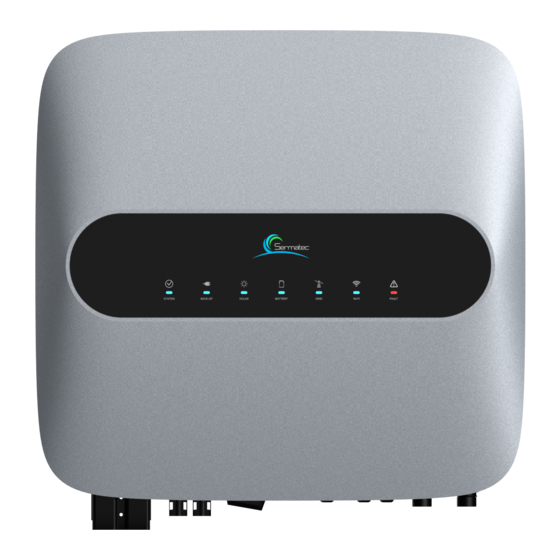
2.2 Installation preparation 2.2.1 Unpacking inspection Only when the goods arrive at the installation site can the unpacking box be allowed to be inspected. The inspection is completed by the customer's representative and the supplier's representative. Unpack the package, review the checklist. Figure2-1 Packing list Figure2-2 The Hybrid Inverter Overview... - Page 15 2.2.2 Cable and Air switch preparation Serial Cable Name Recommended cross-sectional area Color of cable Cable OD model (mm²) (mm) PV side DC UL1015 12AWG 3.31 4.00±0.15 Red、Black positive and negative input Battery side DC UL10269 4AWG 16-25 10.00±0.30 Red、Black positive and negative input AC output...
-
Page 16: Installation
2) Ensure the installation wall is vertical to the ground. If it is sloping ,the tilt angle is only allowed to be less than 15°. 3) Ensure the installation wall is solid enough to meet the requirements of load bearing for the hybrid inverter. 4) The mounting position is supposed to avoid direct sunlight. - Page 17 Figure 2-5 Mounting hole STEP 2: Hammer expansion tube into the wall mount bracket on the wall, keep aligned with the holes. Figure 2-6 STEP 3: Mount the Sematec hybrid inverter on the bracket. Figure 2-7 STEP 4: Secure the inverters with M6 screw on the right side.
- Page 18 Figure 2-8 STEP 5: Install anti-theft lock if necessary ( Optional, equipped by user). Figure 2-9 2.3.2 Electrical Connection Hybrid Inverter System Connection Diagram Figure 2-10 Hybrid Inverter System connection Diagram For AU/EN: 12 12...
- Page 19 Figure 2-11 For Other Countries: Figure 2-12 Power Meter connection diagram: Figure 2-13 (Acrel Single phase Meter)
- Page 20 Dangerous 1) Make sure all switches are at the closed(disconnect) position before the electrical connection. 2)Only qualified installation person can implement the installation of AC and DC input cable. 2.3.2.1 Connect PV cable Attention It is strictly prohibited to connect positive poles( PV1+、PV2+、BAT+) and negative (PV1-、PV2-、 BAT+) reversely or incorrectly.
- Page 21 STEP 3: Use multimeter to measure PV side voltage and verify correct polarity, ensure the open-circuit voltage is less than 580V. Hybrid Inverter System connection Diagram Figure 2-16 PV Polarity check 2.3.2.2 Connect BAT cable Attention Make sure that the installation location meets the following conditions: The area is completely waterproof.
- Page 22 Figure 2-17 Battery terminals connection STEP 2: Use multimeter to measure Battery side voltage and verify correct polarity, ensure open-circuit voltage is less than 58V. 2.3.2.3 AC output cable connection Attention PE cable should be connected properly and reliably, otherwise it would affect normal operation, even cause product damage and serious consequences.
- Page 23 STEP 1: The connector and cable are required to be reliably connected as shown below.Order of connection is L(Red) ,N(Black) ,, Cable sectional are 6 mm², stripping length 6mm Figure 2-19 STEP 2: Measure grid voltage by multimeter, ensure grid voltage is less than the high limit of voltage required by all national grid standards.
- Page 24 Figure 2-21 2.3.2.4 Communication cable connection STEP 1: Remove the waterproof cover plate that comes with the Hybrid Inverter STEP 2: Plug the wire connector of the waterproof cover plate in the accessory into the corresponding interface of the Hybrid Inverter. STEP 3: Fix firmly by screw.
- Page 25 DRED , Power Meter and BMS Connection: Figure 2-23 The RJ45 socket pin assignments for DRED, Power Meter and BMS as follows: Figure 2-24...
- Page 26 If you need to use DRED function, please put the left dip switch to the upper position. Figure 2-25 The inverter shall detect and initiate a response to all supported demand response commands, demand response modes are described as follows: Table 2-4 Mode Requirement...
-
Page 27: Installation Check
Signal Name 485A 485B Figure 2-27 GPRS socket Pin If WiFi used, please install the antenna to the antenna socket. Figure 2-28 WiFi antenna diagram 2.4 Installation check After the Hybrid Inverter is installed, be sure to check the installation according to the following table! Table 2-5 Installation checking list Serie Check content... - Page 28 Serie Check content Check item connection Ensure PV rotating switch is at OFF position Check load connector , grid connector whether they are connected properly. Check if the ground point on the enclosure is earthed reliably. Check the AC and DC connectors whether are reliably connected. Check that the model specifications of the incoming and outgoing cable are correct.
-
Page 29: Sermatec App
3 Sermatec APP Sermatec App is used to check and control inverter parameters. There are two modes: Local Connection Mode and Web Cloud Mode. Local Connection Mode: Use the phone to connect to device by WiFi locally, you can check and set device parameters. -
Page 30: System Commissioning
4 System Commissioning This Chapter is the instructions for commissioning after installation. During the process of commissioning, complying with the safety regulation is necessary. 4.1 Check before commissioning Dangerous Please contact operation personnel to implement commissioning. Please take off metal items like a ring, bracelet, watch, etc, which would cause a short circuit. During the process, pay attention to high voltage danger, avoid personal injury and property loss. - Page 31 STEP 2: Run Sermatec App(local connection mode), connect to the inverter, and check if there is some abnormal warning. STEP 3: If there is no warning, setting Grid standard (must), Battery type (must), then click “Proceed.” STEP 4: Setting Working mode (Must) in your application.
-
Page 32: Product Maintenance
5 Product Maintenance This chapter mainly introduces routine maintenance, troubleshooting. Dangerous ①. You will be obliged to implement product maintenance complying with the safety regulations. ②.The personnel to implement the internal operation of inverters must be trained and qualified with sufficient knowledge of the electrical systems. -
Page 33: Led Status
3. Check if there are signs of cuts on the coat commissioning. contacted with the metal’s surface. Once half a year to 4. Check if the cylinders on the unused DC input one year afterward. terminal and unused GPRS interface are tightened. Grounding Check if the grounding cable is grounded firmly. -
Page 34: Trouble Shooting
Grid Phase Lock Failure or voltage of the grid 2. If step 1 does not help, please contact Sermatec Service team. 1. Shut down inverter and check the AC backup or AC circuit, restart after correction. - Page 35 If it still cannot self-recover, please contact the Sermatec service team. 1. Check grid frequency, and restart The frequency of the the inverter after the grid frequency grid is lower than recover to normal range.
- Page 36 1. Occasional failures can automatically recover. 2. The inverter cannot automatically Bus Hardware Start Up Failure Inverter Damage recover, shut down, and turn on when the power grid is normal. If it still cannot self-recover, please contact the Sermatec service team. 30 30...
- Page 37 Low Battery SOC when PV or grid is normal. Lower Limit Error 3. increase the discharge SOC lower limit setting in Sermatec Mate APP. 4. If above steps cannot help please contact the Sermatec service team. Battery Charge/Discharge Battery current is 1.Occasional failures can...
- Page 38 10K is running without grid and now connecting to grid the 10K will be damaged.) 2. If step 1 does not help,please contact the Sermatec service team. Battery voltage is 1. Check battery voltage, reduce battery voltage or change battery;...
- Page 39 34kΩ. Fault than the limit value If step 1 is done but error still,please contact the Sermatec service team. 1. Occasional failures can automatically recover. 2. The inverter cannot automatically Inverter Damage recover, shut down, and turn on. If it...
- Page 40 Sermatec service team. 1. Occasional failures can automatically recover. Temperature sensor 2. The inverter cannot automatically failure recover, shut down, and turn on.
- Page 41 2. The inverter cannot automatically Start Up Failure hardware recover, shut down, and turn on. If it still cannot self-recover, please contact the Sermatec service team. Problem in inverter 1. Occasional failures can hardware automatically recover. Battery Side Bus Hardware 2.
- Page 42 4.If above steps cannot solve, please contact the Sermatec service team. Maximum 4 Make sure that the number of 10K Parallel Address Overlimit inverters(10K) in inverters connected in parallel are Warning parallel less than 4. Communication 1.Check if the connection is cable between 10K effective.
- Page 43 2. The inverter cannot automatically recover, shut down, and turn on. If it still cannot self-recover, please contact the Sermatec service team. Battery SOC changes 1.Please change work mode to a lot suddenly ‘energy storage’ mode, to charge the...
-
Page 44: Technical Parameters
3. If step 2 does not help, please contact service team for more solutions. 6 Technical Parameters Table6-1 Technical parameters Parameters PV Input (DC) Maximum PV array power(w) 6000 Vmax PV(V) Rated voltage(V) Maximum input current(A) 13/13 Isc PV(V) 14/14 MPPT voltage range 125-550 Number of MPPT trackers... - Page 45 4600 Rated power(VA) Rated voltage(V) 220/230Va.c. Electrical connection 1/N/PE Rated frequency(Hz) 50/60 Maximum current 20.9 Rated current(A) Overcurrent protection(A) Short circuit current(A) 98Apeak, 45Arms Support power mode、Overpower 5 kw Peak power(W)duration @ Ta=25°C (30min) 、6kw(5min) UPS switch time(S) <0.5 <3% Total harmonic distortion THD(Linear load)...
- Page 46 Weight (kg) Cooling concept Natural-cooling Isolation type Transformerless Wi-Fi, GPRS(Optional), RS485 Communication Display Warranty (Years) Notes: “ * ” South African grid connection standard 4600w 40 40...
Need help?
Do you have a question about the SMT-5K-TL-LV and is the answer not in the manual?
Questions and answers