Table of Contents
Advertisement
Quick Links
Advertisement
Table of Contents

Related Manuals for EKKO EP15JLI


Summary of Contents for EKKO EP15JLI
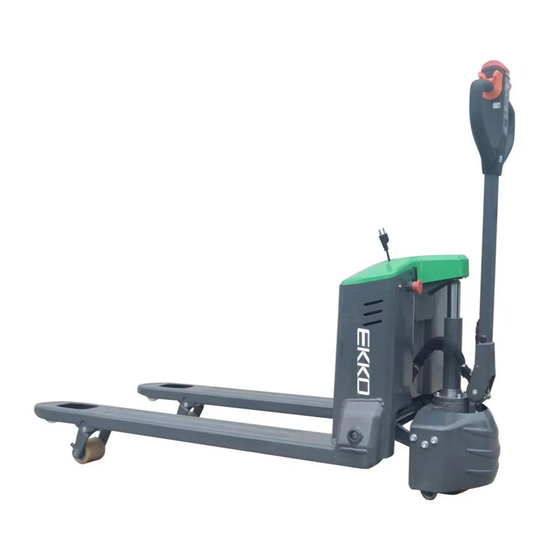
- Page 1 Service manual Electric Pallet Truck EP15JLI/EP18JLI/EP20JLI Warning You must understand the operation instructions in this manual before using it. Note: Please check the last page of this document and nameplate for all current product type identification. Keep it for future use...
-
Page 2: Table Of Contents
Directory 1. Regular maintenance ..........................1 1.1. Maintenance list ..........................1 1.2. Lubrication points .......................... 3 1.3. Check and refill hydraulic oil ......................4 1.4. Check the electrical fuse ....................... 5 2. fault analysis ............................6 2.1. Common fault analysis ........................6 2.2. -
Page 3: Regular Maintenance
1. Regular maintenance Only qualified and trained personnel should perform maintenance work on this vehicle. Before maintenance, remove the cargo from the fork and lower the fork to the lowest position. If you need to lift the vehicle, use the specified lashing or jacking equipment. Before operation, place safety devices (such as designated jacks, wedges or wood blocks) under the vehicle to prevent accidental drop, movement or sliding. - Page 4 • Check alarm system and safety devices • Check the current contactor • Check frame for leakage (insulation test) • 3.10 Check the function and wear of the drive controller • 3.11 Check the electrical system driving the motor traveling system •...
-
Page 5: Lubrication Points
1.2. Lubrication points Lubricate marked points according to maintenance list. Required grease specification: DIN 51825 standard grease. : Figure 1 Lubrication points Drive the oil injection port... -
Page 6: Check And Refill Hydraulic Oil
Bogie bearing 1.3. Check and refill hydraulic oil Recommended hydraulic oil model according to temperature: Ambient –5℃~25℃ >25℃ temperature mark HVLP 32, HLP 46, DIN 51524 DIN 51524 Viscosity 28.8-35.2 41.4 - 47 Waste materials such as waste oil, waste batteries or other materials must be treated and recycled in accordance with national regulations, and returned to the recycling company for recycling if necessary. -
Page 7: Check The Electrical Fuse
1.4. Check the electrical fuse 10A Fuse 200A Fuse List 2:Fuse specification specification Fuse 1 Fuse 01 200A... -
Page 8: Fault Analysis
2. Fault analysis If the vehicle continues to malfunction, follow the instructions in the manual. 2.1. Common fault analysis Fault Cause Processing method Vehicles The battery connector is Check the battery connector and cannot move not connected connect it if necessary The electric lock switch The electric lock switch is is in "OFF"... -
Page 9: Display Of Fault Code
vehicle Controller damage Replacing a Controller started Control forward To restore or replace suddenly backward handle is not reset Display of fault code 2.2. Table 4:1212P fault codes Programmer display Code The fault phenomenon fault diagnosis BATTERY DISCONNECT Battery don't answer 1) The battery is not connected FAULT 2) Poor contact of battery end... - Page 10 PRECHARGE FAULT Pre charge failure 1) The controller is faulty 2) Low battery voltage SPEED POT FAULT The speed limiting 1) Open or short circuit connection of potentiometer is faulty speed limiting potentiometer 2) Open speed limiting potentiometer THERMAL FAULT Over/under temperature 1) Temperature >80℃...
-
Page 11: Circuit/Circuit Diagram
3. Circuit/circuit diagram Electrical schematic diagram 3.1. (24V)... - Page 12 (48V)...
-
Page 13: Hydraulic Principle Diagram
3.2. hydraulic principle diagram Hydraulic oil inspection appearance smell situation The results of Clear and non-discoloration good good You can use Check viscosity, Color transparent good Mix with other oils qualified can continue to... -
Page 14: Disassembly Of Main Parts
Mixed with air and Separate moisture The color changes like milk good water replace hydraulic oil Replacement of hydraulic The color turns dark brown oxidation fluid The color is clear but there with other good Use after filtering are small black spots particles 4. -
Page 15: B、Drive The Disassembly Diagram
B、Drive the disassembly diagram electromagnetic brake drive motor gear case Driving wheel... -
Page 16: C、Hand Assembly Operating Handle Assembly
C、hand assembly Operating handle assembly Tortoise speed switch Belly switch Accelerator knob Motion plus horn button... -
Page 17: Curtis Handheld Unit
5. CURTIS Handheld unit Precautions for operation: The attention function of the hand-held unit is to facilitate vehicle inspection and maintenance. It is not allowed to adjust the controller parameters without the approval of the vehicle manufacturer, so as to avoid vehicle and personal safety accidents. - Page 18 The programmer has two interfaces, one is used to communicate with the electric control, the other is used to communicate with the PC, the programmer has a battery box and a memory card slot The programmer is powered on The connection line of the handheld programmer can be connected to the controller by inserting the programming port of the controller.
- Page 19 The function keys Since the function of the three keys is determined by the specified content, the three keys are blank. At any given time, the function of the button is displayed on the LCD screen above. Direction arrow key The displayed information can be selected up, down, or left by four directional buttons.
- Page 20 Nine menu Fault Diagnosis menu On the main menu, Select Diagnostics and press Select to access the Fault diagnosis menu. The Fault diagnosis menu contains Present Errors current faults and Fault History historical faults Note: Sometimes a fault caused by a temporary event captured in the circuit is not a system fault. You can determine whether the fault exists by restarting the system and observing whether the fault disappears automatically.
- Page 21 Programming menu On the main menu, Select The Programming icon and press Select to access the menu. Save and restore parameter Settings files (.cpf files) through programming menus Save.cpf File (Save.cpf File) Use the save. CPF file function in the programming menu to back up the currently set parameters.
Need help?
Do you have a question about the EP15JLI and is the answer not in the manual?
Questions and answers