Table of Contents
Advertisement
Quick Links
Advertisement
Table of Contents

Related Manuals for Coulomb Technologies ChargePoint CT2023


Summary of Contents for Coulomb Technologies ChargePoint CT2023
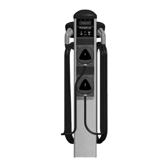
- Page 1 ® by Coulomb Technologies CT2023 ChargePoint Networked Charging Station ® Installation Guide Coulomb Technologies Inc. 1692 Dell Ave. Campbell, CA 95008-6901 USA US toll free: +1-877-370-3802 www.coulombtech.com www.mychargepoint.net Part Number: 75-001089-01 Revision: 1.0...
- Page 2 Copyright and trademarks ©2011 Coulomb Technologies, Inc. All rights reserved. This material is protected by the copyright laws of the United States and other countries. It may not be modified, reproduced or distributed without the prior, express written consent of Coulomb Technologies, Inc. CHARGEPOINT is a U.S.
-
Page 3: Table Of Contents
Contents Introduction Before installing stations............................1-1 Specifications................................1-2 Wiring information ..............................1-3 Installing the Wall Mount Before you begin ................................ 2-1 Overview of steps............................... 2-1 Step 1 - Check boxes for correct contents ....................... 2-2 Step 2 - Remove channel struts from the body ....................... 2-4 Step 3 - Install channel struts ........................... -
Page 5: Introduction
Introduction This document provides step-by-step instructions on how to install a CT2023 ChargePoint® Charging Station. As shown here, the CT2023 ships in five boxes: Cable Assembly 1 and Left Holster Bollard mount, cable hangers, Head & mounting accessories* Assembly Cable Assembly 2 and Right Holster Wall Mount Bracket... -
Page 6: Specifications
ChargePoint® Charging Stations Specifications Electrical Input Input Power 7.2 kW (x 2) Input Voltage 208/240 VAC Input Current 30 A (x 2) Input Power Connections Two independent 40 A branch circuits, each providing Line 1 and Line 2. A single protective Earth conductor. Required Service Panel Breaker 40A double pole breaker (non-GFCI type) on each dedicated circuit Service Panel GFCI... -
Page 7: Wiring Information
Introduction Wiring information NOTE: Requires two dedicated circuits, each with its own 40 A breaker. -
Page 9: Installing The Wall Mount
Installing the Wall Mount Before you begin In addition to the contents of the CT2023 wall mount’s shipping box, you will need the following: • Hammer drill • #3 Phillips screwdriver • 3/8” masonry drill bit • T25 Tamper-resistant Torx driver •... -
Page 10: Step 1 - Check Boxes For Correct Contents
Installation Guide • Installation Guide (1) • Base plate mounting template (1) ® *Body, front panel, and filler panel are Screws for cable by Coulomb Technologies CT2023 pre-assembled. Channel struts are attached to hangers ChargePoint Networked Charging Station ® body for shipping purposes only. - Page 11 Installing the Wall Mount Wall mount bracket and accessories • Wall mount bracket (1) • Screws and washers (6)* • Conduit sealing ring and washer (1) • 3/32” Allen wrench (1) • Template for drilling wall holes (1) *Two extra screws and washers are included in the shipping box.
-
Page 12: Step 2 - Remove Channel Struts From The Body
ChargePoint® Charging Stations Step 2 - Remove channel struts from the body The channel struts are attached to the main body for shipping purposes only. Remove them using a Phillips (2 Ls) screwdriver. NOTE: The cable ties are releasable—cutting is not required. Screws and washers can be discarded. -
Page 13: Step 3 - Install Channel Struts
Installing the Wall Mount Step 3 - Install channel struts To mount the channel strut sections to the concrete wall: • Use the supplied wall mount template to mark the location of the four holes on the wall. Holes must be 24” and 34” up from the floor and be spaced exactly 2 1/2”... -
Page 14: Step 4 - Attach Wall Mount Bracket
ChargePoint® Charging Stations Step 4 - Attach wall mount bracket To install the wall mount bracket: • Using the template as a guide to determine their exact location, install the four channel strut nuts into the channel struts as shown. •... -
Page 15: Step 5 - Remove Front Panel
Installing the Wall Mount Step 5 - Remove front panel To remove the front panel: Loosen the two screws on the • Using a T25 Torx driver, remove the filler panel and two captive screws in the filler slide upwards to panel. -
Page 16: Step 6 - Remove Terminal Block From Body
ChargePoint® Charging Stations Step 6 - Remove terminal block from body Four screws are used to fasten the terminal block to the body. Remove the two center screws and loosen the top and bottom screws. -
Page 17: Step 7 - Drill Holes In Main Body
Installing the Wall Mount Step 7 - Drill holes in main body Use a 5/16” (6 mm) drill to drill out the four mounting holes in the back of the body assembly. These holes are partially pre-drilled. Two are located on the back and two are located on the side. -
Page 18: Step 8 - Attach Body Assembly To Wall Bracket
ChargePoint® Charging Stations Step 8 - Attach body assembly to wall bracket Attach the body assembly to the wall bracket using the four supplied hex head bolts and washers. Tighten using a ratchet and 7/16” socket. NOTE: You may need to adjust the height of the mounting bracket slightly so the body assembly sits on, or just above, the floor. -
Page 19: Step 9 - Attach Coupler And Connect Conduit
Installing the Wall Mount Step 9 - Attach coupler and connect conduit Drill a 1 1/8" diameter (3/4" trade size) hole in the main body no higher than 24" from the bottom. Attach installer-supplied coupler and water-tight sealing washer to the body assembly, as shown, and connect the conduit. -
Page 20: Step 10 - Re-Attach Terminal Block To Main Body
ChargePoint® Charging Stations Step 10 - Re-attach terminal block to main body Slide the terminal block onto the two fastening screws, install the two middle screws, then tighten all of the screws until snug. 2-12... -
Page 21: Step 11 - Connect Wires To Wiring Terminals
Installing the Wall Mount Step 11 - Connect wires to wiring terminals To connect the wiring: • Pull the Ground wire and the 240 VAC L1 and L2 wires into the body assembly. • Strip wires .3” (7.6 mm) and insert into the terminal block as shown Strip Length .3”... -
Page 22: Step 12 - Replace Front Panel
ChargePoint® Charging Stations Step 12 - Replace front panel To replace the front panel: • Slide the front panel into place, as shown. • Re-attach the ground wire by pushing it onto its tab. Re-attach the ground wire to its tab You have now finished installing the wall mounting assembly for the ®... -
Page 23: Installing The Holsters And Cable Assemblies
Installing the holsters and cable assemblies Before you start You will need a short or right-angle Phillips screwdriver. Before installing the holsters and cable assemblies, complete the installation procedure for the CT2023’s main body as described in the previous chapter. Overview of steps ®... -
Page 24: Step 1 - Check Boxes For Correct Contents
ChargePoint® Charging Stations Step 1 - Check boxes for correct contents ® The ChargePoint Charging Station’s cable Cable Assembly 1 \ Left Holster: assemblies/holsters ship in two boxes. Each box contains: • Holster • Cable assembly • Screws (3) - DISCARD THESE* •... -
Page 25: Step 2 - Attach Holsters/Cable Hangers To Body Assembly
Installing the holsters and cable assemblies Step 2 - Attach holsters/cable hangers to body assembly Align the right holster with the cable Loosely fasten hanger and attach as follows: these three screws • Insert the three screws/washers to attach the cable hanger/holster to the main body but do not tighten. -
Page 26: Step 3 - Install Cable Assembly 2
ChargePoint® Charging Stations Step 3 - Install cable assembly 2 Slide cable assembly 2 into the body all the way until it is flush with the top of the front panel. IMPORTANT NOTES: • When sliding the cable assembly into the body, ensure that the serial cable that hangs down from the topmost terminal block does not get caught between the cable... - Page 27 Installing the holsters and cable assemblies Step 3 - cont’d To connect the cable assembly: • Plug the cable assembly’s rectangular connector into the body assembly’s terminal block, ensuring it is fully seated. • Connect the circular connector (that hangs down from the upper terminal block) to the cable assembly by aligning the white arrow.
-
Page 28: Step 4 - Install The Filler Panel
ChargePoint® Charging Stations Step 4 - Install the filler panel Slide the filler panel into the body assembly until it is flush with the top of cable assembly 2, as illustrated. NOTES: • The filler panel is included in the shipping box for the main body (see page 2-2). -
Page 29: Step 5 - Install Cable Assembly 1
Installing the holsters and cable assemblies Step 5 - Install cable assembly 1 Slide cable assembly 1 into the body all the way until it is flush with the top of the filler panel, as illustrated. IMPORTANT: Ensure the cable assembly is fully seated and that no gap exists between the bottom of the cable assembly and the top of the filler... - Page 30 ChargePoint® Charging Stations Step 5 - cont’d Plug the cable assembly’s rectangular connector into the left receptacle on the body assembly’s terminal block, ensuring it is fully seated. Connect the ground wire to the tab at the top of the cable assembly. IMPORTANT! Do not insert the charging station’s SAE J1772 connector into the holster until after...
-
Page 31: Installing The Head Assembly
Installing the head assembly Before you start You will need: • Head assembly • Torx Driver T25 - Tamper-Resistant. This driver is available at www.wihatools.com (Item 36281) and www.mcmaster.com (Item 83335A64). In addition, you must complete the installation of the body assembly, the holsters, and the cable assemblies (see previous chapters). -
Page 32: Step 1 - Check Box For Correct Contents
To complete the installation steps described in this chapter, you will also need the additional front cover plate included in the shipping box for the main body (see page 2-2). Coulomb Technologies, Inc. Order Desc.: CTXXX-zzzzzzzzzzzzzzzz A provisioning label is Serial No:... -
Page 33: Step 2 - Install Head Assembly Into Body
Installing the head assembly Step 2 - Install head assembly into body To install the head assembly: Semi-circular Tab #1 • Remove the plastic wrap from the face of groove (or the head assembly and retain the affixed “key slot)” in connector provisioning label for future use (see Tab #2... -
Page 34: Step 3 - Verify That The Station Operates Correctly
ChargePoint® Charging Stations Step 3 - Verify that the station operates correctly Before securing the head assembly, follow these instructions to ensure that the charging station is fully operational: • Turn on the main power to ensure that the head assembly powers up. When the circuit is live and the head assembly’s wiring is connected, a sequence of power-up messages will be displayed. -
Page 35: Step 4 - Secure Head Assembly And Filler Panel
Installing the head assembly Step 4 - Secure head assembly and filler panel Push down on the cable assemblies, and the head assembly to ensure they are fully seated and that there are no gaps. All assemblies fit tightly and may require extra downward force to ensure they are fully seated. -
Page 36: Step 5 - Install Front Cover Plates
ChargePoint® Charging Stations Step 5 - Install front cover plates NOTE: An FCC label has been applied to one of the front cover plates—install this cover plate over the head assembly. Install the cover plate without the FCC label over the filler panel. Align the protruding features on the front cover panel with the openings on the head assembly. -
Page 37: Step 6 - Arrange For Station Provisioning
• Provisioning password • Location information (mailing address, and if possible, exact coordinates) The station’s model number, serial number, MAC address, and Coulomb Technologies, Inc. provisioning password is duplicated on two labels. One label is Order Desc.: CTXXX-zzzzzzzzzzzzzzzz affixed to the head assembly (once installed, you can no longer see... -
Page 39: Troubleshooting
Troubleshooting The station’s display To troubleshoot your charging station, pay attention to the messages that are displayed on the two-line display. The display sequentially shows the name of the charging station and the current state of each of its ports. The following example shows how a CT2023 displays the state of its #1 charging port under normal conditions: The top line displays the current state of the station’s charging ports. -
Page 40: Understanding Error Messages
ChargePoint® Charging Stations Understanding error messages The following pages describe the error messages that can occur on a CT2023 charging station. If one of the LEDs above the charging station’s display illuminates RED, read the display for information about the type of error that has occurred. - Page 41 Troubleshooting Ground fault errors The following ground fault errors can occur during charging, or when attempting to begin a charging session: Cause/Other Symptoms: The station detected a ground fault during a charging session. The left or right LED will flash RED and the station will not charge. Solution/Action: The charging station will wait 16 seconds before attempting to restore power.
- Page 42 ChargePoint® Charging Stations User errors The following errors occur as a result of an inappropriate action that was performed by a person using the charging station. Cause/Other Symptoms: The cable assembly was subjected to a strong pulling force and has detached (as part of the station’s safety features).
- Page 43 Troubleshooting Other errors The following errors occur as a result of a potential equipment failure or utility failure. Cause/Other Symptoms: After power-up, this message is displayed if a connector is damaged or if the station is not wired properly. When attempting to charge a vehicle, this message is displayed if the relay is stuck open.
-
Page 44: Resolving A Relay Stuck Open Fault
ChargePoint® Charging Stations Resolving a Relay Stuck Open fault A relatively common installation issue is a RELAY STUCK OPEN fault. When this fault is in effect, the station is unable to deliver power, and will display the following message upon power-up: NOTE: The exact message may vary slightly depending on the station’s software version. -
Page 45: Checking Voltages
Troubleshooting Checking voltages Use a solenoid type voltage tester (sometimes referred to as a “Wiggy”) to check the charging station’s voltages at the terminal block. This type of tester will draw sufficient current to expose a LEVEL 2 CORE poor connection. SEE INSTALLATION GUIDE. -
Page 47: Appendix A - Limited Product Warranty
LIMITED PRODUCT WARRANTY This Limited Product Warranty applies to you, a customer who has purchased COULOMB’s ChargePoint™ Networked Charging Stations and/or related products (“Products”) from COULOMB TECHNOLOGIES, INC. (“COULOMB”) or one of its authorized distributors and not for resale. LIMITED ONE-YEAR WARRANTY Subject to the exclusions from warranty coverage set forth below, COULOMB warrants that the Product will be free from any defects in materials and/or workmanship (the “Limited Warranty”) for a period of one (1) year after the date of the initial... - Page 48 ChargePoint® Charging Stations You are responsible for the proper installation and maintenance of the Product. Any service or repairs beyond the scope of the Limited Warranty or the Five-Year Extended Warranty above are subject to COULOMB’s then prevailing current labor rates and other applicable charges.
- Page 49 COULOMB. The Limited Product Warranty is not transferable by you to anyone else. All inquiries or claims made under this Limited Product Warranty must be sent to COULOMB’s address as follows: Coulomb Technologies, Inc. 1692 Dell Avenue. Campbell, California 95008-6901...
- Page 52 Coulomb Technologies Inc. 1692 Dell Ave. Campbell, CA 95008-6901 USA US toll free: +1-877-370-3802 www.coulombtech.com www.mychargepoint.net...
Need help?
Do you have a question about the ChargePoint CT2023 and is the answer not in the manual?
Questions and answers