Table of Contents
Advertisement
Quick Links
Advertisement
Table of Contents
Troubleshooting

Related Manuals for Coulomb Technologies ChargePoint CT2025


Summary of Contents for Coulomb Technologies ChargePoint CT2025
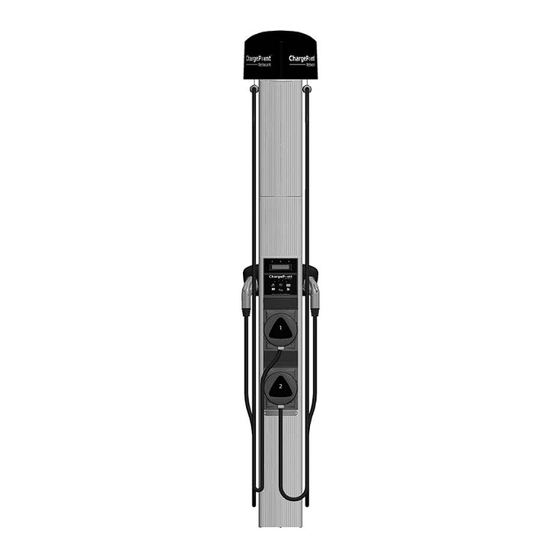
- Page 1 ® by Coulomb Technologies CT2025 ChargePoint Networked Charging Station ® Installation Guide Coulomb Technologies Inc. 1692 Dell Ave. Campbell, CA 95008-6901 USA US toll free: +1-877-370-3802 www.coulombtech.com www.mychargepoint.net Part Number: 75-001082-01 Revision 5.0...
- Page 2 Copyright and trademarks ©2011 Coulomb Technologies, Inc. All rights reserved. This material is protected by the copyright laws of the United States and other countries. It may not be modified, reproduced or distributed without the prior, express written consent of Coulomb Technologies, Inc. CHARGEPOINT is a U.S.
-
Page 3: Table Of Contents
Contents Introduction Before installing stations............................1-1 Specifications................................1-2 Wiring information ..............................1-3 Installing the Bollard Mount Before you start................................2-1 Overview of steps............................... 2-1 Step 1 - Check boxes for correct contents ....................... 2-2 Step 2 - Remove mounting pole/base plate from body assembly ................. 2-4 Step 3 - Remove access panel.......................... - Page 4 ChargePoint® Networked Charging Station Troubleshooting The station’s display ..............................6-1 Understanding error messages..........................6-2 Troubleshooting the light ............................6-6 Resolving a Relay Stuck Open fault .......................... 6-7 Checking voltages ..............................6-8 APPENDICES A Prepare Installation Site (Bollard Mount) Before you start................................A-1 Installing into the ground............................
-
Page 5: Introduction
Introduction ® This document provides step-by-step instructions on how to install a CT2025 ChargePoint Charging Station. The CT2025 ships in five boxes: Cable Assembly 1 and Left Holster ollard mount & mounting Head Assembly accessories Cable Assembly 2 Assembly and Right Holster FIRST - Install Bollard Mount NEXT - Install Holsters NEXT - Install... -
Page 6: Specifications
ChargePoint® Charging Stations Specifications Electrical Input Input Power 7.2 kW (x 2) Input Voltage 208/240 VAC Input Current 30 A (x 2) Input Power Connections Line A1, Line A2, Earth, Line B1, Line B2 (two independent 40 A branch circuits, each providing Line 1 and Line 2, and a single protective Earth conductor). -
Page 7: Wiring Information
Introduction Wiring information NOTE: Requires two dedicated circuits, each with its own 40 A breaker. -
Page 9: Installing The Bollard Mount
Installing the Bollard Mount Before you start ® Before installing a CT2025 ChargePoint Charging Station, prepare the installation site as described in Appendix A of this document. After the installation site has been prepared, you will need the following tools, in addition to contents in the bollard mount and top assembly shipping boxes, to install the bollard mount: •... -
Page 10: Step 1 - Check Boxes For Correct Contents
*Body, mounting pole, base plate, top and bottom front panels, access panel with front cover, and filler panel are pre-assembled. Front cover plate Installation ® Filler by Coulomb Technologies Guide CT2025 panel ChargePoint Networked Charging Station ® Allen wrench Installation Guide Coulomb Technologies Inc. - Page 11 Installing the Bollard Mount Top assembly The top assembly ships in a box containing: • Pre-assembled top assembly CAUTION: DO NOT remove the dowel pins that are attached to the top assembly’s cables. It is important that these pins stay in place until after the cable retractors have been fully installed (see Chapter 5).
-
Page 12: Step 2 - Remove Mounting Pole/Base Plate From Body Assembly
ChargePoint® Charging Stations Step 2 - Remove mounting pole/base plate from body assem- TIP ! It is easier to complete this step if the bollard mount is laying down in a horizontal position, held in place by its original packaging material as shown. To remove the mounting pole/base plate from the body assembly: •... -
Page 13: Step 3 - Remove Access Panel
Installing the Bollard Mount Step 3 - Remove access panel TIP ! It is easier to complete this step if the bollard mount is laying down in a horizontal position, held in place by its original packaging material as shown. To remove the access panel: •... -
Page 14: Step 4 - Install Top Assembly
ChargePoint® Charging Stations Step 4 - Install top assembly Before installing the top assembly, install the bulb and cover: • Screw the bulb into the socket. • Position the cover over the light bulb as shown. • Using a T25 Torx driver, tighten the two captive screws to secure the cover to the top assembly. - Page 15 Installing the Bollard Mount • Slide the foam packaging upwards so it fully supports the top of the body assembly. Then position the top assembly onto the top of the body assembly, ensuring that the top assembly’s wiring runs along the inside of the body.
- Page 16 ChargePoint® Charging Stations • Use the pre-installed tie wrap to secure the top assembly’s wiring. Topmost tie wrap • Slide the front panel upwards as far as it can go. NOTE: To prevent water ingress, the bottom edge of the top front panel must be aligned with the features cut into the main body.
- Page 17 Installing the Bollard Mount • Connect the top assembly's rectangular connector to the top of the topmost terminal block. Use the tie wrap to secure the top assembly’s as shown. Connect the top assembly’s rectangular connector Secure wiring to tie wrap...
-
Page 18: Step 5 - Mount Base Plate/Pole Assembly
ChargePoint® Charging Stations Step 5 - Mount base plate/pole assembly To mount the base plate/pole assembly: • Pull all three wires up through the conduit and the mounting pole. • Place the base plate/mounting pole assembly over the wiring conduit and attach the base plate to the J-Bolts using the installer-supplied nuts and washers as shown. -
Page 19: Step 6 - Install Body
Installing the Bollard Mount Step 6 - Install body NOTE: Due to the length of the bollard mount, it is recommended that two people participate in this step. To install the body: • Ensure the two front brackets are within reach of the base plate so they are ready to be installed. - Page 20 ChargePoint® Charging Stations Step 6 - cont’d • Install brackets to stabilize the bollard. To do so, loosely secure the body to the mounting pole by aligning the top front bracket with its corresponding back bracket and tightening its two screws with a Philips screwdriver.
-
Page 21: Step 7 - Remove Filler Panel And Fasten Bottom Front Panel
Installing the Bollard Mount Step 7 - Remove filler panel and fasten bottom front panel To remove the filler panel and fasten the bottom front panel: • Loosen the filler panel’s two captive security screws using a T25 Torx driver. Then slide the filler panel upwards to remove. -
Page 22: Step 8 - Connect Wires To Wiring Terminals
ChargePoint® Charging Stations Step 8 - Connect wires to wiring terminals To connect the wiring:. • Pull the Ground wire and the 240 VAC L1 and L2 wires into body assembly • Strip wires .3” (7.6 mm) and insert in terminal block as shown. Strip Length .3”... - Page 23 Installing the Bollard Mount You have now finished installing the body assembly for the CT2025 ® ChargePoint Charging Station’s body assembly. You are ready to install the holsters and cable assemblies. See Chapter 3. 2-15...
-
Page 25: Installing The Holsters And Cable Assemblies
Installing the holsters and cable assemblies Before you start Before installing the holsters and cable assemblies, complete the installation procedure for the CT2025’s main body, as described in the previous chapter. Overview of steps ® Installing the ChargePoint Charging Station’s holsters involves a few simple steps: 1. -
Page 26: Step 1 - Check Boxes For Correct Contents
ChargePoint® Charging Stations Step 1 - Check boxes for correct contents ® The ChargePoint Charging Station’s cable Cable Assembly 1 - Left Holster: assemblies/holsters ship in two boxes. Each box contains: • Holster • Cable assembly • Screws (3) • Washers (3) •... -
Page 27: Step 2 - Attach Holsters To Body Assembly
Installing the holsters and cable assemblies Step 2 - Attach holsters to body assembly To attach the right holster to the body assembly: • Align the three openings on the right holster with the corresponding openings on the right side of the body assembly. -
Page 28: Step 3 - Route The Rf Cables Under The Top Front Panel
ChargePoint® Charging Stations Step 3 - Route the RF cables under the top front panel To ensure the top assembly’s RF cables are out of the way when installing the cable assemblies, fold them up and route them behind the top front panel. Route the RF cables under the top front... -
Page 29: Step 4 - Install Cable Assembly 2
Installing the holsters and cable assemblies Step 4 - Install cable assembly 2 Insert cable assembly 2 into the main body’s access panel opening, then slide it into the body all the way until it is flush with the top of the bottom front panel. - Page 30 ChargePoint® Charging Stations Step 4 - cont’d Connect the wiring for the bottom cable assembly as follows: • Plug the cable assembly’s rectangular connector into the body assembly’s terminal block, ensuring it is fully seated. • Connect the circular connector Release this cable (that hangs down from the upper from its retaining...
-
Page 31: Step 5 - Install Filler Panel
Installing the holsters and cable assemblies Step 5 - Install filler panel Slide the filler panel into the body assembly until it is flush with the top of cable assembly 2, as illustrated. NOTES: • You removed the filler panel when installing the bollard mount (see page 2-13). -
Page 32: Step 6 - Install Cable Assembly 1
ChargePoint® Charging Stations Step 6 - Install cable assembly 1 Insert cable assembly 1 into the main body’s access panel opening, then slide it into the body all the way until it is flush with the top of the filler panel, as illustrated. - Page 33 Installing the holsters and cable assemblies Step 6 - cont’d Plug the cable assembly’s rectangular connector into the left receptacle on the body assembly’s terminal block, ensuring it is fully seated. Connect the ground wire to the left tab on the cable assembly. IMPORTANT! Do not insert the charging station’s SAE J1772 connector into the holster until after...
-
Page 35: Installing The Head Assembly And Access Panel
Installing the head assembly and access panel Before you start You will need: • Head assembly • Access panel and access panel cover • Torx Driver T25 - Tamper-Resistant. This driver is available at www.wihatools.com (Item 36281) and www.mcmaster.com (Item 83335A64). In addition, you must complete the installation of the body assembly, the holsters, and the cable assemblies (see previous chapters). -
Page 36: Step 1 - Check Box For Correct Contents
(see page 2-2).This cover plate does not include an FCC label. • the access panel and its front cover (this is Coulomb Technologies, Inc. also included in the shipping box for the Order Desc.: CTXXX-zzzzzzzzzzzzzzzz Serial No: YYWWSSnnnnnn... -
Page 37: Step 2 - Install Head Assembly
Installing the head assembly and access panel Step 2 - Install head assembly To install the head assembly: • Remove the plastic wrap from the face of the head assembly and retain the affixed provisioning label for future use (see page 4-11). •... -
Page 38: Step 3 - Connect Lamp Wiring To Head Assembly
ChargePoint® Charging Stations Step 3 - Connect lamp wiring to head assembly Connect the 802.15.4 cable (black cable with a yellow band) to the top of the head assembly, ensuring that the bend in this cable is positioned towards the back. If you are installing a gateway station, If you have not connect the modem cable (black cable... -
Page 39: Step 4 - Verify That The Station Operates Correctly
Installing the head assembly and access panel Step 4 - Verify that the station operates correctly Before securing the head assembly, perform these steps to ensure that the charging station is fully operational: • Turn on the main power to ensure the head assembly powers up. -
Page 40: Step 5 - Secure Head Assembly And Filler Panel
ChargePoint® Charging Stations Step 5 - Secure head assembly and filler panel Before securing the head assembly, ensure that the top is flush with the access panel’s bottom cutout, and that Ensure the head no gap exists between the bottom of the assembly is flush with head assembly and the top of the filler the top of the access... -
Page 41: Step 6 - Install Front Cover Plates
Installing the head assembly and access panel Step 6 - Install front cover plates NOTE: An FCC label has been applied to one of the front cover plates—install this plate over the head assembly. Install the cover plate without the FCC label over the filler panel. -
Page 42: Step 7 - Install Access Panel
ChargePoint® Charging Stations Step 7 - Install access panel Using a T25 Torx driver, turn the four Rear view of access panel screws in the access panel box counter-clockwise fully to position its rear brackets vertically, as shown. Turn all four screws clockwise to position the... - Page 43 Installing the head assembly and access panel Step 7 - cont’d Align the grooves in the access panel’s front cover with the slots in the access panel. Remove the yellow tape (tab) from the access panel’s front cover. Push the front cover forwards until it snaps into place.
- Page 44 ChargePoint® Charging Stations You have now finished installing the head assembly and the access panel. The CT2025 charging station is ready for provisioning (see next step) and you can now install the cable retractors. See Chapter 5. 4-10...
-
Page 45: Step 8 - Arrange For Station Provisioning
• Provisioning password • Location information (mailing address, and if possible, exact coordinates) The station’s model number, serial number, MAC address, and Coulomb Technologies, Inc. provisioning password is duplicated on two labels. One label is Order Desc.: CTXXX-zzzzzzzzzzzzzzzz affixed to the head assembly (once installed, you can no longer see... -
Page 47: Installing The Cable Retractors
Installing the cable retractors Before you start Before installing the cable retractors, you must complete the installation procedures for the CT2025’s bollard mount and cable assemblies, as described in previous chapters. Overview of steps Installing the CT2025’s cable retractors involves a few simple steps: 1. -
Page 48: Step 1 - Verify That You Have All Required Components
ChargePoint® Charging Stations Step 1 - Verify that you have all required components To install the cable retractors, you will need the following components that are included in the shipping box with the Top Assembly (see page 2-3): • Cable clamps (4) •... -
Page 49: Step 2 - Install Cable Brackets
Installing the cable retractors Step 2 - Install cable brackets REMINDER ! The connector on cable assembly 1 plugs into the left holster and the connector on cable assembly 2 plugs into the right holster. To install the brackets onto the charging cable: a) Located on the underside of the top assembly, unbundle the nylon cord below the dowel pin to access the... - Page 50 ChargePoint® Charging Stations c) Secure the two brackets together by inserting the four screws and tightening them securely using a Philips screwdriver. d) Remove the white tape from the charging cable e) Repeat steps b) through d) for the other charging cable.
-
Page 51: Step 3 - Remove Dowel Pins
Installing the cable retractors Step 3 - Remove dowel pins Pull downwards on the nylon cord and remove the dowel pin located at the top of the cord. When the dowel pin is removed, the cord will retract into the top assembly. Pull out the dowel pins You have now finished installing the... -
Page 52: Optional: Attach A Sign
ChargePoint® Charging Stations OPTIONAL: Attach a sign The CT2025 top front panel features two pre-drilled holes containing pre-set 1/4-20 x .375” screws. This allows you to attach a 9” x 12” (228.6 mm x 304.8 mm) sign to the front of the charging station. If installing a sign, refer to the hole pattern measurements provided below and use the two screws that are pre-set into the top front panel. -
Page 53: Troubleshooting
Troubleshooting The station’s display To troubleshoot a CT2025, you’ll need to pay attention to the messages that are displayed on the two-line display. The display sequentially shows the name of the charging station and the current state of each of its ports. -
Page 54: Understanding Error Messages
ChargePoint® Charging Stations Understanding error messages The following pages describe the error messages that can occur on a CT2025 charging station. If one of the LEDs above the charging station’s display illuminates RED, read the display for information about the type of error that has occurred. - Page 55 Troubleshooting Ground fault errors The following ground fault errors can occur during charging, or when attempting to begin a charging session: Cause/Other Symptoms: The station detected a ground fault during a charging session. The left or right LED will flash RED and the station will not charge. Solution/Action: The charging station will wait 16 seconds before attempting to restore power.
- Page 56 ChargePoint® Charging Stations User errors The following errors occur as a result of an inappropriate action that was performed by a person using the charging station. Cause/Other Symptoms: The vehicle was driven away during a charging session. The station is out of service until the cable assembly is replaced.
- Page 57 Troubleshooting Other errors The following errors occur as a result of a potential equipment failure or utility failure. Cause/Other Symptoms: After power-up, this message is displayed if a connector is damaged or if the station is not wired properly. When attempting to charge a vehicle, this message is displayed if the relay is stuck open.
-
Page 58: Troubleshooting The Light
ChargePoint® Charging Stations Troubleshooting the light Follow the steps below to verify that the CT2025’s light is working properly. • Upon power up, the light in the top assembly will illuminate briefly before the light sensor detects light. Under sufficient lighting conditions, the light should turn off after approximately 60 to 90 seconds. If the light sensor fails, the light will not turn off. -
Page 59: Resolving A Relay Stuck Open Fault
Troubleshooting Resolving a Relay Stuck Open fault A relatively common installation issue is a RELAY STUCK OPEN fault. When this fault is in effect, the station is unable to deliver power, and will display the following message upon power-up: NOTE: The exact message may vary slightly depending on the station’s software version. In most cases, this fault is caused by either a damaged power plate connector or a wiring problem. -
Page 60: Checking Voltages
ChargePoint® Charging Stations Checking voltages Use a solenoid type voltage tester (sometimes referred to as a “Wiggy”) to check the charging station’s voltages at the terminal block. This type of tester will draw sufficient current to expose a LEVEL 2 CORE poor connection. -
Page 61: A Prepare Installation Site (Bollard Mount)
APPENDIX Prepare Installation Site (Bollard Mount) Before you start ® The ChargePoint Charging Station’s bollard mount can be installed either: • into the ground • onto an existing concrete surface (on an intermediate floor only) This appendix provides basic guidelines for preparing the installation site in both scenarios. IMPORTANT: Always check local codes to ensure compliance. - Page 62 ChargePoint® Charging Stations Install J-Bolts and conduit into concrete as Conduit must extend illustrated. To ensure correct alignment, 12-24” (30-61 cm) above use the template provided in the shipping the concrete (check local codes) box with the bollard mount (illustrated below).
-
Page 63: Installing Onto An Existing Concrete Surface
Prepare Installation Site Installing onto an existing concrete surface IIMPORTANT: Follow instructions exactly as described to ensure rated performance. Check all local and national electrical and building codes to ensure compliance. NOTE: The CT2025 can be installed on intermediate level floors of a parking garage where bolts can be inserted through an entire concrete slab. -
Page 65: B Limited Product Warranty
LIMITED PRODUCT WARRANTY This Limited Product Warranty applies to you, a customer who has purchased COULOMB’s ChargePoint™ Networked Charging Stations and/or related products (“Products”) from COULOMB TECHNOLOGIES, INC. (“COULOMB”) or one of its authorized distributors and not for resale. LIMITED ONE-YEAR WARRANTY Subject to the exclusions from warranty coverage set forth below, COULOMB warrants that the Product will be free from any defects in materials and/or workmanship (the “Limited Warranty”) for a period of one (1) year after the date of the initial... - Page 66 ChargePoint® Charging Stations You are responsible for the proper installation and maintenance of the Product. Any service or repairs beyond the scope of the Limited Warranty or the Five-Year Extended Warranty above are subject to COULOMB’s then prevailing current labor rates and other applicable charges.
- Page 67 COULOMB. The Limited Product Warranty is not transferable by you to anyone else. All inquiries or claims made under this Limited Product Warranty must be sent to COULOMB’s address as follows: Coulomb Technologies, Inc. 1692 Dell Avenue. Campbell, California 95008-6901...
- Page 72 Coulomb Technologies Inc. 1692 Dell Ave. Campbell, CA 95008-6901 USA US toll free: +1-877-370-3802 www.coulombtech.com www.mychargepoint.net...
Need help?
Do you have a question about the ChargePoint CT2025 and is the answer not in the manual?
Questions and answers