Table of Contents
Advertisement
Quick Links
Advertisement
Table of Contents

Related Manuals for Coulomb Technologies ChargePoint CT500


Summary of Contents for Coulomb Technologies ChargePoint CT500
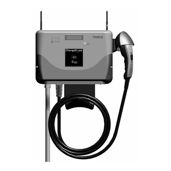
- Page 1 ® by Coulomb Technologies CT500 ChargePoint Networked Charging Station ® Installation Guide Coulomb Technologies Inc. 1692 Dell Ave. Campbell, CA 95008-6901 USA US toll free: +1-877-370-3802 www.coulombtech.com www.mychargepoint.net Part Number: 75-001024-01 Revision: 1.0...
- Page 2 Copyright and Trademarks ©2010 Coulomb Technologies, Inc. All rights reserved. This material is protected by the copyright laws of the United States and other countries. It may not be modified, reproduced or distributed without the prior, express written consent of Coulomb Technologies, Inc.
- Page 3 Coulomb Technologies for assistance. Important! Changes or modifications to this product not authorized by Coulomb Technologies could void the FCC compliance. At the end of its service life, this product should be recycled according to local laws and regulations. Contact...
-
Page 5: Table Of Contents
Contents Introduction Before installing the CT500 ............................1-1 Specifications................................1-2 Wiring information ..............................1-3 Installation Instructions Overview of steps............................... 2-1 Step 1 - Check box for correct contents ........................2-2 Step 2 - Attach holster ............................... 2-3 Step 3 - Remove front panel ............................. 2-4 Step 4 - Mount to wall.............................. -
Page 7: Introduction
Introduction ® This document provides step-by-step instructions on how to install any CT500 ChargePoint Charging Station. Before installing the CT500 • Ensure that the appropriate wiring, circuit protection, and metering is in place at the installation location. For details, refer to the specifications (page 1-2) and wiring diagrams (page 1-3). •... -
Page 8: Specifications
ChargePoint® Charging Stations Specifications Electrical Input Input Power 7.2 kW Input Voltage 208/240 VAC Input Current 30 A Input Power Connections Line 1, Line 2, Earth Required Service Panel Breaker 40A double pole breaker (non-GFCI type) on dedicated circuit Service Panel GFCI Do not provide external GFCI as it may conflict with internal GFCI (CCID) Standby Power 5 W typical... -
Page 9: Wiring Information
Introduction Wiring information 208 V, 3Ø METER LOCAL SERVICE PANEL L2 L3 MAIN BREAKER 240 V 40A, 2 POLE BREAKER MAY BE CONNECTED TO ANY TWO PHASES. CT500 TERMINAL BLOCK 240 V, 1Ø METER LOCAL SERVICE PANEL MAIN BREAKER 240 V CT500 TERMINAL BLOCK... -
Page 11: Installation Instructions
Installation Instructions After the appropriate wiring is in place at the installation site (see “Wiring information” on page 1-3), you are ready to install the CT500. You will need: ® • CT500 ChargePoint Charging Station components (see page 2-2) • ¾” (19 mm) conduit •... -
Page 12: Step 1 - Check Box For Correct Contents
• Holster bolts (3) • Antenna(s)* • Mounting template • Installation Guide *The CT500 ships with either one or two antennas, depending on the specific model that was ordered. ® by Coulomb Technologies CT500 ChargePoint ® Networked Charging Station Installation Guide Coulomb Technologies Inc. -
Page 13: Step 2 - Attach Holster
Installation Instructions Step 2 - Attach holster Using a #2 Phillips screwdriver, attach the holster to the main assembly using the three supplied Holster bolts. -
Page 14: Step 3 - Remove Front Panel
ChargePoint® Charging Stations Step 3 - Remove front panel Using a #2 Phillips screwdriver, loosen the 2 captive screws located on each side of the front panel. Pull the front panel downward to remove. -
Page 15: Step 4 - Mount To Wall
Installation Instructions Step 4 - Mount to wall Drill four 3/16” holes in the wall, as Masonry illustrated. Use the supplied template to ensure correct alignment. IMPORTANT: The top of the CT500 must be mounted no higher than a maximum height of 48” above the surface to comply with the Americans with Disabilities Act (ADA). - Page 16 ChargePoint® Charging Stations Step 4 - Cont’d Align the CT500 to the mounting surface, and fasten to the wall using a 3/8” socket wrench to fasten the four ¼ ” x 2” lag bolts, fasten it to the wall.
-
Page 17: Step 5 - Install Conduit
Installation Instructions Step 5 - Install conduit Choose the appropriate conduit opening and, if necessary, remove its cover. The CT500 has four conduit NOTE: The CT500 has four conduit openings—two openings, three of which are covered. If openings from the you remove a cover, use it to cover the back and two from the remaining unused conduit opening. -
Page 18: Step 6 - Connect Wires To Wiring Terminals
ChargePoint® Charging Stations Step 6 - Connect wires to wiring terminals Pull the 240V L1 and L2 wires, and the Ground wire, into body assembly and connect to wiring terminals. Strip wires ¼” (6 mm), insert in terminal block, and tighten screws to 18 ½... -
Page 19: Step 7 - Replace Front Panel
Installation Instructions Step 7 - Replace front panel Align the front panel with the main assembly and push upwards into place until the edges meet. Using a #2 Phillips screwdriver, tighten the two captive screws located on each side of the front panel. Insert the connector into the holster. -
Page 20: Step 8 - Attach Antennas
ChargePoint® Charging Stations Step 8 - Attach antennas Attach the antennas to the top of the main assembly as shown. Turn the antenna clockwise to hand-tighten. Always install the NOTE: The CT500 ships with either one antenna with the yellow or two antennas, depending on the band on the right side left side... -
Page 21: Step 9 - Verify That The Station Operates Correctly
Installation Instructions Step 9 - Verify that the station operates correctly Follow these instructions to ensure that the charging station is fully operational: • Turn on the main power to ensure that the head assembly powers up. When the circuit is live and the head assembly’s wiring is connected, a sequence of power-up messages will be displayed. -
Page 23: Troubleshooting
Troubleshooting The station’s display To troubleshoot the CT500, you’ll need to pay attention to the messages are displayed on the 2-line display. The display varies slightly depending on whether or not the CT500 is equipped with a card reader. Under normal conditions, the CT500 displays the following message to indicate that it is ready for charging: AVAILABLE REMOVE CONNECTOR FROM HOLSTER... - Page 24 ChargePoint® Charging Stations Ground fault errors The following ground fault errors can occur during charging, or when attempting to begin a charging session: SUSPENDED GROUND FAULT / AUTO RE-TRY IN 00:mm:ss Cause/Other Symptoms: The station detected a ground fault during a charging session. Solution/Action: The charging station will wait 15 minutes before reattempting to restore power.
- Page 25 Troubleshooting Other errors The following errors occur as a result of a potential equipment failure or utility failure. FAULT RELAY STUCK OPEN / FOR ASSISTANCE CALL ... Cause/Other Symptoms: When attempting to charge a vehicle, this message will be displayed if the relay is stuck open.
- Page 28 Coulomb Technologies Inc. 1692 Dell Ave. Campbell, CA 95008-6901 USA US toll free: +1-877-370-3802 www.coulombtech.com www.mychargepoint.net...
Need help?
Do you have a question about the ChargePoint CT500 and is the answer not in the manual?
Questions and answers