Dräger PSS 7000 Series Instructions For Use
Self-contained breathing apparatus
Hide thumbs
Also See for PSS 7000 Series:
- Reference manual (21 pages) ,
- Instructions for use (5 pages) ,
- Instructions for use (4 pages)
Advertisement
Quick Links
®
PSS
7000 Series
Self-contained breathing apparatus
For Your Safety
The Dräger PSS
®
7000 Series of SCBA incorporates a preset and sealed
pressure reducer. The Dräger guarantee is void should the original sealing
caps of this unit be tampered with, removed, or broken. Correct operational
condition is only valid when the pressure reducer is serviced and re-sealed
by Dräger.
●
Use of this SCBA requires wearer training and observance of this
Instruction for Use.
●
Use the SCBA for the purpose specified in this instruction, or as
confirmed in writing by Dräger.
●
Use and maintenance of the SCBA requires knowledge and
compliance with National Regulations, Laws, and Standards,
governing the use of respiratory protection apparatus in the country of
use.
●
Only trained competent personnel should inspect and service the
SCBA at regular intervals and a record kept of such inspections and
service.
●
Only trained and competent personnel should carry out the inspection
and charging of the associated compressed air cylinders.
●
Dräger recommends that a Service Contract be arranged with the
Dräger Branch or Agent.
●
Contact Dräger for details of Wearer Training, Service Training
Courses and Service Contracts.
●
Use only original Dräger Spare Parts for service and maintenance.
●
Use only original Dräger Test Equipment for service and maintenance.
●
Notify Dräger if there is a component fault or failure.
●
The air supply shall meet the requirements for breathing air according
to EN12021.
Liability Statement
Terms and Conditions of warranty for the Dräger PSS
SCBA can be obtained from Dräger on request. Responsibility for reliable
function of the apparatus transfers to the owner, or operator, when
serviced or repaired by untrained personnel, (not employed or authorised
by Dräger), or when used in a manner not conforming to its intended use.
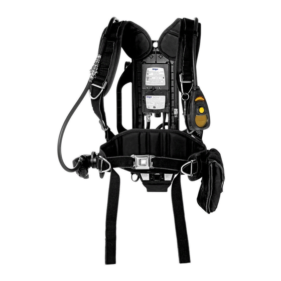
Description
The Dräger PSS
®
7000 Series of SCBA has a height adjustable and
articulating carrying system that provides greater performance, comfort
and ease of use, resulting in reduced wearer fatigue.
The backplate of the carrying system incorporates a sliding height
adjustable yoke that has three preset height settings. When wearing the
SCBA, the flexible pivot joint, located at the base of the backplate, is in line
with the hip of the wearer. The pivot joint moves in response to the twisting
and bending of the wearer, improving the weight distribution, freedom of
movement and increased manoeuvrability for the wearer.
The variants described in this Instruction for Use are fitted with either a
single cylinder strap, or a universal cylinder strap that is capable of
accepting either a single or two cylinder arrangement. A 'T' Piece is
available for use in the two cylinder configuration.
Refer to the specific Instructions for Use for the operation, control and
testing of the electronic monitoring unit, i.e. Bodyguard.
Intended Use
The Dräger PSS
®
7000 Series of SCBA, when used with approved lung
demand valve and associated face mask, and compressed air cylinder(s)
combination, provides the wearer with respiratory protection when working
in a contaminated, or oxygen deficient gaseous atmosphere.
Working duration of the apparatus is dependent on the capacity (volume)
of the cylinder(s) selected, and the breathing rate of wearer.
Approvals
The European standards, guidelines, and directives according to which
this product is approved are specified in the declaration of conformity (see
declaration of conformity or www.draeger.com/product-certificates).
Explanation of marking and symbols
Refer to the relevant authority for explanation of approval body symbols
and marking on the equipment. Examples of other marking on component
parts of the breathing apparatus are:
BRAC-1359
–
Dräger serial number
08/09
–
Month and year of manufacture
3356812 or R21034
–
Dräger part number
SF
–
Standard force coupling
LF
–
Low force coupling
Use in potentially explosive atmospheres
The PSS
®
7000 Series is type tested as suitable for use in potentially
explosive atmospheres. Electronic sub-assemblies are ATEX certified.
All combinations are suitable for use in hazardous areas up to and
including zone 0 and zone 20.
Technical Data
High Pressure Connection:
200bar or 300bar
Standard G5/8 as per EN 144-2.
Whistle Warning Unit
Preset by Dräger to begin activation between 60bar to 50bar.
Compressed Air Cylinders
4L to 9L capacity cylinders (200bar or 300bar) are available in either steel
or composite materials. Contact Dräger for details.
Preparation for Use
Trained and competent SCBA users must perform the following
procedures before release of the apparatus for operational use.
Important Note: The pressure gauge face may be fitted with a thin
flexible protective covering. This covering must be removed before
first use.
Height adjustment
The carrying system length can be adjusted and set, at the shoulder yoke,
to suit the torso length of the wearer. Three settings, marked on the set,
are available i.e. Short (S), Medium (M) and Long (L).
To set the torso length, follow these instructions. Refer to Fig 1.
●
Lift the apparatus into the vertical position.
PSS
®
is a trademark of Dräger
1
3
5
®
7000 Series of
●
Simultaneously press the two spring loaded buttons to unlock the
shoulder yoke. Slide the yoke in the required direction then release the
buttons. Continue sliding the yoke until the buttons engage and lock
the yoke in the required position, S, M, or L.
Note: When the set is being worn, and with the adjusting straps
extended (loose), adjustment of the yoke height may be performed by
a support person.
Fitting a Single Cylinder
Note: The following instructions are for a screw-on cylinder coupling.
Installation of a quick-connect cylinder coupling is detailed in the
quick-connect coupling Instructions for Use.
●
Inspect and check that the threads of the cylinder valve port and the
reducer hand wheel are not damaged. Check that the O Ring seal in
pressure connector is in position and not damaged. Check that the
bore to the sintered filter in the HP connector of the pressure reducer
is clean and free from dirt and contamination.
●
Lay the carrying frame horizontal and fully extend the cylinder support
strap. Slide the buckle of the centre dividing strap (if fitted) along the
strap, away from the cam lock buckle, to form one loop.
●
Insert the cylinder (valve end first) through the loop of the support
strap, from the top end of the backplate, and then slide the cylinder
aligning the valve with the hand wheel of the reducer.
Caution: To prevent damage, ensure that the hand wheel connector
of the pressure reducer remains clear of the cylinder.
●
Lift the cylinder and backplate into the vertical position (supported on
the end of the cylinder), align and screw the hand wheel of the
pressure reducer (clockwise) to the port of the valve until an initial
restriction is felt. Continue turning the hand wheel, using only the
thumb and index finger, until a definite metal to metal contact is
achieved – Do Not use tools or over tighten.
●
Place the unit back into the horizontal position, take up the slack of the
cylinder support strap and activate the cam lock mechanism by pulling
the free end of the support strap back over the cylinder, securing the
cylinder to the backplate – refer to Fig 3.
●
Place and secure the loose end of the cylinder support strap to the
hook-and-loop strip.
Fitting Two Cylinders
●
Inspect, and check, that the threads in the port of each cylinder valve,
the 'T' Piece, and the reducer hand wheel are not damaged. Check
that the O Ring seal in the high pressure connector is in position and
not damaged. Check that the bore to the sintered filter in the HP
connector is clean and free from dirt and contamination.
●
Align and screw the hand wheel of the pressure reducer (clockwise) to
the centre port of the 'T' Piece until an initial restriction is felt – then turn
back 1/4 turn anticlockwise. Do Not tighten.
●
Fully extend the cylinder support strap and then slide the buckle of the
centre dividing strap to the centre position to form two loops – refer to
Fig 2.
●
With the backplate in a horizontal position, insert the first cylinder
(valve end first) through the first loop of the support strap, from the top
end of the backplate and then slide the cylinder aligning the valve with
the 'T' Piece.
Caution: To prevent damage, ensure that the hand wheel connectors
of the 'T' Piece remain clear of the cylinder.
●
Align the first hand wheel of the 'T' Piece with the port of the valve and
screw the hand wheel (clockwise) to the valve. Tighten the hand wheel
– finger tight only – then turn back 1/4 turn anticlockwise. Do Not
tighten.
●
Insert the second cylinder (valve end first) through the second loop of
the support strap, from the top end of the backplate and slide the valve
towards the 'T' Piece.
●
Align the second hand wheel of the 'T' Piece with the port of the valve
and screw the hand wheel (clockwise) to the cylinder valve. Tighten
the hand wheel – finger tight only – then turn back 1/4 turn
anticlockwise. Do Not tighten.
●
Align the cylinders centrally with the backplate. Tighten the hand
wheels of the 'T' Piece to the cylinder valves – finger tight only. Screw
the hand wheel of the pressure reducer (clockwise) to the port of the
'T' Piece until an initial restriction is felt. Continue turning the hand
wheel, using only the thumb and index finger, until a definite metal to
metal contact is achieved – Do Not use tools or over tighten.
●
Take up the slack of the cylinder support strap and activate the cam
lock mechanism by pulling the free end of the support strap back over
the cylinder, securing the cylinder to the Backplate – refer to Fig 3.
●
Place and secure the loose end of the cylinder support strap to the
hook-and-loop strip.
2
3076
2141
4
2009
1913
6
1
2
3088
4278
Instructions for Use
i
Pre-Operational Checks
Connecting the LDV to the Apparatus
●
For breathing apparatus with a medium-pressure coupling for the lung
demand valve, disconnect and then reconnect the male coupling. To
connect, press the male coupling into the female coupling until an
audible click is heard. If there is any difficulty disconnecting or
connecting, see the troubleshooting information.
Refer also to the Instructions for Use provided with the Lung Demand
Valve.
Important Note: The following tests will verify the integrity of the
assembly. These instructions refer to apparatus fitted with a
mechanical pressure gauge. Refer to the appropriate Instruction for
Use provided for variants, i.e. Bodyguard.
High Pressure Leak and Whistle Warning Test
●
Positive Pressure type LDVs only (A, AE, ESA) – Press the reset
button of the LDV to ensure that the positive pressure facility is 'Off'.
●
Slowly and fully 'open' the cylinder valve (both valves if a two cylinder
configuration) by rotating the hand wheel of the valve(s)
(anticlockwise) until a resistance is felt. A momentary sounding of the
whistle-warning unit will occur during the pressurisation of the system.
Check the pressure reading of the cylinder contents (pressure) gauge.
●
'Close' the cylinder valve (both valves if a two cylinder configuration)
by rotating the hand wheel of the valve(s) clockwise until a resistance
is felt. When fully closed, immediately check the pressure reading of
the contents gauge.
●
After one minute observe the contents gauge and then 'reopen' the
cylinder valve(s) – the pointer of the gauge must not show an increase
in pressure reading more than 10bar (10bar is acceptable) – i.e. one
radial marking on the gauge face.
●
Continue to the Whistle Warning Unit Check.
●
While holding the contents gauge in one hand, slowly 'close' the
cylinder valve(s) fully until a resistance is felt.
●
A, AE and ESA LDVs – Cover the outlet port of the LDV with the palm
of the hand. Press the centre of the rubber cover to switch 'On' the
positive pressure. Slowly vent the system by carefully lifting the palm
of the hand from the outlet of the LDV to maintain a slow decrease in
pressure.
●
N – Slowly vent system by carefully pressing the centre of rubber
cover.
●
As the pressure decreases, observe the contents gauge. The whistle
should begin to operate and sound between the following pressures:
Test Parameter – 60bar to 50bar.
Note: Should the whistle not sound at the preset pressure, return to Dräger
Service
●
When the system is exhausted of air, activate the reset feature of the
LDV (A, AE and ESA) to ensure that the positive pressure facility is
'Off'.
Connecting LDV to the face mask
●
Fully extend (open) the straps of the head harness. Refer also to the
Instructions for Use provided with the face mask.
Use
Putting on the apparatus
Safety notice: this device may only be worn by expert personnel who
have been thoroughly trained in the correct use of the device.
●
If necessary, adjust and set the yoke to the required Wearer Height.
●
Loosen the shoulder straps and waist strap and hang the unit over your
body. Take the weight of the system on your shoulders by pulling the
shoulder straps. Do Not tighten. Check that both the shoulder pads are
not twisted.
●
Close the waist strap buckle. Pull the ends of the waist strap forwards
(Fig 4), until the strap padding fits securely and comfortably over your
hips. Tuck the strap ends between your body and the hip pads.
●
Pull the shoulder strap until the device rests securely and comfortably
on your hips. Do Not over-tighten. Pull the strap retainers down to
secure the strap ends (Fig 5).
●
Fully loosen the head bands of the face mask, leaving the centre strap
in position. Place the neck strap over the back of your neck.
●
Activate the reset feature of the LDV to ensure that the positive
pressure facility is switched 'Off'.
Important Note: Refer to the appropriate Instruction for Use provided
with any variants, e.g. Bodyguard.
●
'Open' the cylinder valve(s) slowly but fully to pressurise system.
Check the gauge.
Note: When in the twin cylinder configuration – fully open both cylinder
valves.
Putting on the face mask
Refer to the Instructions for Use provided with the face mask.
In Use
●
Regularly take a reading of the content gauge to check the pressure
remaining in the cylinder(s).
●
The whistle will sound at the preset pressure of the whistle warning unit
– leave the hazard area by the shortest route. The wearer should be in
a safe area before the whistle begins to sound.
●
Once established in a safe area 'Check In' with the BA control
personnel.
After Use
Removal of the apparatus
Safety Warning: Do Not remove the apparatus until in a safe area,
clear of the hazard.
●
Lift and pull forward on each of the bottom buckles of the face mask
straps – extending the straps. When the seal to the face is broken,
activate the reset feature of the LDV (PP only) to ensure that the
positive pressure facility is 'Off'. Continue to remove the face mask.
Breathe normally. Leave the face mask hanging around the neck from
the neck strap.
●
'Close' the cylinder valve(s) until a resistance is felt i.e. the valve is fully
closed. Depress the centre of the rubber cover of the LDV to exhaust
the air from the system. Activate the reset feature of the LDV (A, AE
and ESA only) to switch 'Off' the positive pressure.
●
Open the waist belt buckle to release the waist belt. Lift the shoulder
strap ends to release the strap retainers (Fig 5) and then lift the
shoulder strap buckles to loosen the straps.
●
Remove the neck strap of the face mask from around the back of the
neck then remove the apparatus from the shoulders. Place the
apparatus down carefully at a safe location. Do Not drop the apparatus.
3355849 (A3-D-P) Page 1 of 2
Advertisement

Subscribe to Our Youtube Channel
Related Manuals for Dräger PSS 7000 Series


Summary of Contents for Dräger PSS 7000 Series
- Page 1 ® 7000 Series Instructions for Use Self-contained breathing apparatus For Your Safety Pre-Operational Checks Connecting the LDV to the Apparatus The Dräger PSS ® 7000 Series of SCBA incorporates a preset and sealed pressure reducer. The Dräger guarantee is void should the original sealing caps of this unit be tampered with, removed, or broken.
- Page 2 ® 7000 Series Instructions for Use Self-contained breathing apparatus Maintenance Troubleshooting After use, refer also to the table of Test and Maintenance Intervals The troubleshooting guide shows fault diagnosis and repair information applicable to breathing apparatus users. Further troubleshooting and repair information is available in Instructions for Use supplied with associated equipment.
Need help?
Do you have a question about the PSS 7000 Series and is the answer not in the manual?
Questions and answers