Table of Contents
Advertisement
Available languages
Available languages
Quick Links
PSS
Pneumatic Upgrade kit
®
1
For your safety
1.1
General safety statements
● Before using this product, carefully read the Assembly Instructions.
● Strictly follow the A ssembly Instructions and the appropriate Instructions
for Use. The user must fully understand and strictly observe the
instructions. Use the product only for the purposes specified in the
Intended Use section of this document.
● Use only genuine Dräger spare parts and accessories, or the proper
functioning of the product may be impaired.
● Do not use a faulty or incomplete product, and do not modify the
product.
● Notify Dräger in the event of any component fault or failure.
1.2
Definitions of alert icons
Alert icons are used in this document to provide and highlight text that
requires a greater awareness by the user. A definition of the meaning of
each icon is as follows:
WARNING
!
Indicates a potentially hazardous situation which, if not avoided,
could result in death or serious injury.
CAUTION
!
Indicates a potentially hazardous situation which, if not avoided, could
result in physical injury or damage to the product or environment. It
may also be used to alert against unsafe practices.
NOTICE
i
i
Indicates additional information on how to use the product.
2
Description
2.1
Product overview
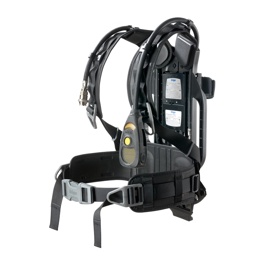
The Dräger PSS Pneumatic Upgrade kit allows the pneumatic system of
PSS 90 series and PSS 100 series self-contained breathing apparatus
(SCBA) to be upgraded to the PSS 7000 series of pneumatics.
Two main variants are available: a reducer-only kit and a pre-assembled
reducer and hose kit. If the breathing apparatus label (located on the
backplate) does not state "EN137:2006 Type 2", the breathing apparatus
is compatible with a reducer and hose kit only. Breathing apparatus
approved to EN137:2006 Type 2 is compatible with all kit variants.
2.1.1
Reducer-only kit
The reducer-only kit is suitable for upgrading the reducer on PSS 90
and PSS 100 breathing apparatus approved to EN137:2006 Type 2 and
comprises the following parts:
● 1 PSS 7000 pressure reducer (with either a standard hand wheel or
quick-connect coupling)
● 2 Retention staples
● 2 M3 Torx socket pan head screws
● 1 PSS 90 reducer mounting bracket
(PSS 100 bracket available separately)
● 1 Reducer mounting block base
● 1 Reducer mounting block top
● 1 M5 shoulder bolt
● 1 M6 flat washer
● 1 M5 flat washer
● 1 M5 self locking hexagon nut
● 1 Upgrade approval label
● 1 Hose loop
2.1.2
Reducer and hose kit
The reducer and hose kit is suitable for upgrading both the reducer and
pneumatic hoses on PSS 90 and PSS 100 series breathing apparatus
manufactured after 2002. It comprises the components listed above with
the addition of the following parts:
● 1 Medium-pressure hose with quick coupling
● 1 Dual-pressure hose and pressure gauge
In the reducer and hoses kit the hoses, Torx screws and retention staples
are pre-fitted to the reducer.
2.2
Intended use
The PSS Pneumatic Upgrade kit is used to replace the pneumatic system
on PSS 90 series or PSS 100 series breathing apparatus (contact Dräger
for a full list of compatible breathing apparatus). It is intended to upgrade
to the PSS 7000 pressure reducer type during scheduled overhaul using
the Dräger Repair and Exchange service (REX).
3
Assembly instructions
WARNING
!
Fitting the PSS Pneumatic Upgrade kit may only be carried
out by trained personnel (attendance at an appropriate Dräger
maintenance course is required). Fitting by untrained personnel
could make the breathing equipment unsafe for use.
3.1
Removing the existing pneumatic system
1. Referring to the breathing apparatus Instructions for Use, place
equipment down carefully on a flat surface. Vent all air from the system
and then remove the cylinder.
2. Unscrew and remove the locking nut (Fig 1, Item 1) and washer (2).
Slide the locking bolt (3) out from the mounting block to release the
reducer (4).
3. Open all hose loops to release the hoses and remove the pneumatic
assembly from the backplate and harness.
4. Remove the rubber boot from the bottom of the backplate.
5. Unclip the mounting bracket (5) from the backplate.
6. Discard the mounting bracket and fixings as they are no longer required.
3360273
© Dräger Safety UK Limited
Edition 03 – April 2013 (Edition 01 – October 2011)
Subject to alteration
PSS
is a registered trade mark of Dräger
®
3
4
2
5
1
1
0333
1
2
2
3
4
0228
1
3
3
2
2137
1
3
2
4
3838
4
7
6
2
1
PSS 90
1
PSS 100
1
3.2
Replacing the pneumatic hoses
3.2.1
Disconnecting the hoses from existing pressure reducer
If the new reducer is pre-fitted with the hoses go to Section 3.3. If any
pneumatic accessory or a secondary supply hose is installed see the
appropriate Instructions for Use for details of their removal.
1. Unscrew and remove the 2 screws (Fig 2, Item 1) from the reducer.
Remove the retaining cap (2) and then remove the retention staple (3).
2. Remove the medium-pressure hose (4) from the outlet port.
3. Repeat the above steps to disconnect the dual-pressure hose.
Component parts of the hose ends should not be removed.
Draeger Safety UK Limited
Ullswater Close
Tel
+44 1670 352891
Riverside Business Park
Fax +44 1670 356266
Blyth
Northumberland NE24 4RG
Internet http://www.draeger.com
i
Assembly Instructions
3.2.2
Connecting hoses to replacement pressure reducer
2
1
1. Check the condition of the medium-pressure hose. Ensure that the
O-ring (Fig 3, Item 1), O-ring retainer (2) and spring (3) are clean,
undamaged and in position on the hose end.
2. Align and insert the medium-pressure hose (Fig 4, Item 1) into the
port, pressing and holding it against the compression spring. Insert
the retaining staple (2) through the holes in the reducer, ensuring the
correct location into the groove in the hose end. Check that the hose
5
3
4
is securely retained by gently pulling the hose away from the reducer.
3. Insert and tighten the screw (3). Dräger recommend tightening the
3836
screw to a torque of 1.2 Nm.
4. Check the condition of the dual-pressure hose. Ensure that the O-rings
(Fig 5, Items 1 and 2), backup ring (3) and filter element(s) (4) are
clean, undamaged and in position on the hose end.
1
5. Insert the dual-pressure hose (Fig 6, Item 1) into the port. Insert the
retaining staple (2) through the holes in the reducer, ensuring that it
3
fits into the groove in the hose end. Check that the hose is securely
retained by gently pulling the hose away from the reducer.
6. Insert and tighten the screw (3) to a torque of 1.2 Nm.
6
2
CAUTION
!
If installing a secondary supply hose, ensure that the hose is
3837
routed as shown in Fig 7. This will prevent the secondary supply
hose from protruding beyond the backplate where it could sustain
damage or present a snagging hazard.
3.3
Fitting the upgraded pneumatic system
1. To install the reducer mounting bracket:
○ P SS 90 – Hook the mounting bracket around the bottom of the
backplate (see Fig 8). Pivot the mounting bracket into the slots
7
in the backplate. Apply gentle pressure to the bracket until it clips
securely into place.
3826
○ P SS 100 – Line up and insert the mounting bracket into the slots
in the backplate.
2. Refit the rubber boot to the bottom of the backplate.
3. Place the equipment down carefully on a flat surface. Slot the mounting
block base (Fig 9, Item 1) and top (2) into the groove in the backplate
as shown.
4. Place the reducer (5) into the slot in the mounting block. Place the
M6 washer (4) over the shoulder bolt (3) and slide them through the
reducer and mounting block. Note that the mounting bolt can only
be inserted fully through the reducer and mounting block from the
8
direction shown in Fig 9. Slide the M5 washer (7) over the end of the
bolt and hand-tighten the locking nut (6) to hold the reducer in place.
3824
5. Securely tighten the locking nut and bolt. Do not over tighten.
5
NOTICE
i
i
An assembly tool (part number 3360746) available from Dräger
3
may be used to securely tighten the locking nut and bolt if required.
6. Align the hoses and refit hose loops as shown in Fig 10 (PSS 90) or
Fig 11 (PSS 100). Add the additional hose loop (Fig 10, Item 1) in the
fourth position from the top of the shoulder strap if upgrading a PSS 90
9
series breathing apparatus.
3781
3.4
Labelling the upgraded product
1. Record on the new approval label:
○ What upgrade kit was fitted (e.g. reducer and hoses).
○ W hat the breathing apparatus was before the upgrade, including
any variant markings (e.g. PSS 90 D).
2. Ensure the backplate is free from dirt and grease.
3. Fix the new approval label to the backplate as follows:
○ F or PSS 90, fix the label to the inside of the backplate (Fig 10,
Item 2).
○ For PSS 100, fix the label beneath the anchor peg (Fig 11, Item 1).
3.5
Functional testing
WARNING
2
!
Failure of the breathing apparatus to meet any of the standards
or parameters described in the functional tests indicates a system
fault. Report the fault to trained service personnel or contact
10
Dräger. Do not use the breathing apparatus until the fault condition
is rectified.
3827
Prepare the equipment for use and carry out the full functional testing as
detailed in the appropriate Instructions for Use.
4
Using the modified equipment
The instructions for using and caring for the modified equipment (use,
maintenance, cleaning, storage, etc.) are contained in the appropriate
Instructions for Use.
11
3828
Dräger Safety AG & Co. KGaA
Revalstraße
D-23560
Lübeck
Germany
Tel
+49 451 882-0
Fax +49 451 882-2080
Internet http://www.draeger.com
3360273 (A3-D-P)
Advertisement
Table of Contents

Related Manuals for Dräger PSS


Summary of Contents for Dräger PSS
- Page 1 ● 1 Reducer mounting block top any variant markings (e.g. PSS 90 D). ● 1 M5 shoulder bolt 2. Ensure the backplate is free from dirt and grease. ● 1 M6 flat washer 3. Fix the new approval label to the backplate as follows: ● 1 M5 flat washer ○ F or PSS 90, fix the label to the inside of the backplate (Fig 10, ● 1 M5 self locking hexagon nut Item 2). ● 1 Upgrade approval label ○ For PSS 100, fix the label beneath the anchor peg (Fig 11, Item 1). ● 1 Hose loop 3.5 Functional testing 2.1.2...
- Page 2 Reines Druckminderer-Kit anziehen. Das reine Druckminderer-Kit ist als Erweiterung des Druckminderers HINWEIS auf dem PSS 90 und PSS 100 für EN137:2006 Typ 2 zugelassenen Ein Montagewerkzeug (Teilenummer 3360746), erhältlich von Atemschutzgerät geeignet und besteht aus den folgenden Teilen: Dräger, kann verwendet werden, um Mutter und Schraube, falls erforderlich, fest an zuziehen.
Need help?
Do you have a question about the PSS and is the answer not in the manual?
Questions and answers