Advertisement
Quick Links
Installation &Maintenance Instructions
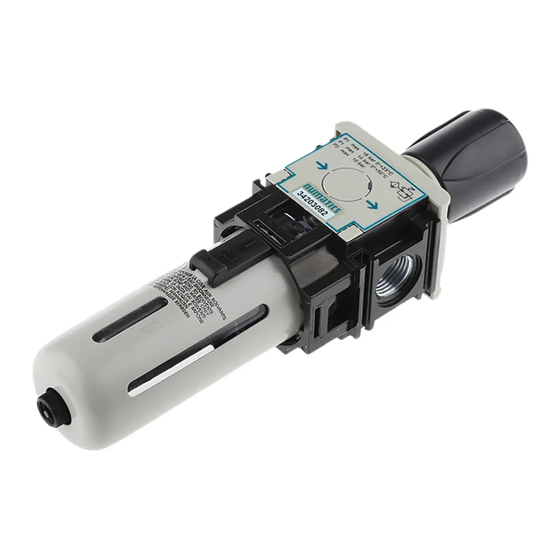
STAINLESS STEEL FILTER REGULATOR ( High Flow)
These operating instructions are delivered with each
product. Malfunctions, damage or injury may occur
if these instructions are not followed.
DESCRIPTION
Series 342 Air Filter Regulators are designed for use in potentially
explosive atmospheres caused by gases, vapors, mists and/or dusts as
per ATEX Directive 2014/34/EU and standards EN ISO 80079-36.
Classification (Zone 1 and 21) : II 2 G Ex h IIC T5 Gb, II 2 D Ex h
IIIC T5 Db (T5- 90°C Ambient Temperature).The Classification
temperature depends on the ambient temperature. These regulators
are made of stainless steel with option compliant to NACE MR0175.
All metal on conductive parts must be inter connected and grounded.
Startup and maintenance are to be performed as detailed below.
This component is not a safety accessory. It is intended only for the
compliant use either as an individual component or incorporated in
an apparatus, machinery and installations. ASCO Stainless Steel Air
Filter Regulators are designed to be operated in accordance with the
limits specified in the nameplate or as specified in this document.
All applicable directives, legislations, orders and standards, as
amended from time to time, as well as state-of-the-art practices and
procedures must be observed for intended scope of application of the
product. Where applicable take all appropriate measure to ensure the
requirements are met. This device complies with the essential safety
requirements of the EU PED 2014/68/EU. Declaration of conformity
is available on
request..
All assembly, operation, use and maintenance must be
performed by qualified, authorized personnel. Personnel working
with the components must be familiar with the applicable safety and
regulations relating to the components, apparatus and machinery
installations. In case of problems, please contact ASCO or one of its
authorized representatives in your region.
General Operating Specifications
Fluid : Instrument air, neutral, natural & Sour gas.
Ambient Temperature: For manual drain: the temperature range
should be within -40 C to + 90 C (-40F to +194F);For Auto
drain: the range should be within 0°C to + 90°C (32°F to +194°F) ;
Inlet Pressure: Do not exceed the maximum operating pressure 20
bar(290psi) for manual drain FR, 11bar(160psi) for auto drain FR
Quick relief option available for standard operating temperature
-40°C to +90°C
INSTALLATION
• Check the preliminary storage conditions required for the
component. They must be in accordance to the product's
specifications.
• Carefully remove the Regulator from the packaging.
•Power off and depressurize the apparatus, machinery or installation
designed to receive the FR.
•Install the FR near where the air is to be used.
•Install ASCO pressure gauge comes accessory on the frontal gauge
port.
•Do Not modify the device.
•Make sure that the fluid is compatible with the materials it contacts.
•Operator or user must ensure that the gas group corresponds to the
product's classification.
•Check Nameplate for correct catalog number, pressure, temperature
and service. Never apply incompatible fluids or exceed pressure
rating of the regulator.
• The installer must install the air filter regulator at the user's
location in accordance with the requirements specified in Directive
99/92/EC.
Positioning
For optimum life and performance, the FR should be
mounted vertically upright (Max. Inclination 5°)
ASCO Numatics (India) Pvt. Ltd.,
No. 57, Kundrathur Main Road, Gerugambakkam,
Chennai-600128, India
SIZE : 3/4" & 1"
General
ST.STEEL VERSION
Piping
Connect piping to valve according to markings on FR body.
Apply pipe compound sparingly to male pipe threads only. If
applied to FR threads, the compound may enter the FR and
cause functional difficulty. Avoid pipe strain by properly
supporting and aligning piping. When tightening the pipe, do
not use the FR as a lever. Locate wrenches applied to piping
as close as possible to connection point.
Direct Frontal mounting or mounting with brackets possible.
MAINTENANCE
NOTE: Ensure the air supply is completely stopped. It is not
necessary to remove the FR from the pipeline for repairs.
Cleaning
All FRs should be cleaned periodically. The time
between cleanings will vary depending on the medium and
service conditions. The most common part that requires
cleaning is the filter element.
Use running water for regular cleaning or a mild
detergent for cleaning the filter element. Do not use diluted
acids, strong detergents or corrosive chemicals.
For auto drain version clean the filter ring periodically.
Causes of Improper Operation
• Incorrect pressure: Check upstream pressure. Pressure
to FR must be within range specified on nameplate.
• Excessive Leakage: Disassemble FR and clean all parts.
If parts are worn or damaged, install a complete ASCO
Spare Parts kit.
Manual drain operation:
Hold the knurling face of drain with fingers & rotate it to the
anti clockwise direction looking from top to unscrew the
manual drain to purge out the water that accumulated in the
bowl. After draining out, screw the manual drain back to its
original position & ensure proper working of AFR.
Automatic draining:
ASCO SS-AFR auto drain provides hassle free draining
of equipment which purge out the water accumulated in the
bowl automatically. Flexible tube (Barb connection)/
Hard piping (Adapter1/8"NPT-optional) can be used for
collecting the condensate. It also provides manual drain
feature integrated with automatic drain. Use spanner to
operate the same with the flat provided on it.
Auto Drain Manual
Manual Drain
Override
To Drain Rotate: (Looking From Top)
Anticlockwise to drain, Clockwise to close
Torque Chart
Torque Value
Part Name
Bowl/Body
Bowl/Bonnet
Full Hand tight
Filter Sub-Assembly
Exhaust Filter
(As Applicable)
Manual drain
Full Hand tight
Auto Drain
Adapter
Form No. IM-IND- 523425 Rev CB
ECN No : 305463
342 SERIES
Adapter1/8"NPT-Optional
Torque Value
Pound-inches
Newton-Meters
664 ± 45
75 ± 5
Full Hand tight
70 ± 10
8± 1
Full Hand tight
160 ± 10
18± 1
160 ± 10
18± 1
Page 1 of 3
Advertisement

Related Manuals for Asco 342 Series


Summary of Contents for Asco 342 Series
- Page 1 Manual drain operation: installations. In case of problems, please contact ASCO or one of its Hold the knurling face of drain with fingers & rotate it to the authorized representatives in your region.
- Page 2 CAUTION : To ensure proper valve operation, install all parts supplied in ASCO Spare Parts kit. Do not mix old and new parts. ORDERING INFORMATION FOR ASCO SPARE PARTS KIT ...
- Page 3 Adapter 1/8” Circlip NPT (Optional) Figure 1. SS Filter Regulator assembly Page 3 of 3 ASCO Numatics (India) Pvt. Ltd., Form No. IM-IND- 523425 Rev CB No. 57, Kundrathur Main Road, Gerugambakkam, ECN No : 305463 Chennai-600128, India...
Need help?
Do you have a question about the 342 Series and is the answer not in the manual?
Questions and answers