Table of Contents
Advertisement
Quick Links
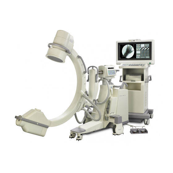
OEC
®
9800 C-Arm
Service Manual
• Front Matter
• Introduction/Safety
• C-Arm Subsystem
• AC Power Distribution
• DC Power Distribution
• Battery Charging
• System Communications
• Interlocks
• Stator Power and Control
• Pre-Charging
• X-Ray On, X-Ray Disable
• kV Generation
• mA Generation
• Automatic Brightness Stabilization
Contents
Installation
Service
• Collimator
• Image Control
• Cooling
• Flip Flop Motion
• Orbital Motion
• Wig Wag Motion
• Horizontal Cross Arm Motion
• L-Arm Motion
• Vertical Column Motion
• Steering and Braking
• Diagnostics
• Calibration
• Replacement
Schematics
Periodic Maintenance
Illustrated Parts
Advertisement
Table of Contents


Need help?
Do you have a question about the 9800C-Arm and is the answer not in the manual?
Questions and answers