Table of Contents
Advertisement
Quick Links
9600 System Periodic Maintenance Procedure
00-880606-02
GE OEC Medical Systems, Inc.
Rev. C
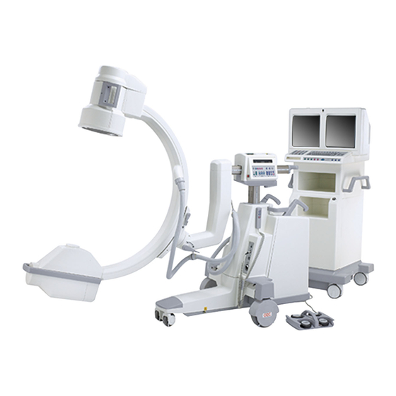
9600 Standard system, left-front view
9600 Standard system, right-rear view
9600 Super-C system, left-front view
9600 Super-C system, right-rear view
9600 Workstation, rear view
9600 Workstation, front view
Page 1
Advertisement
Table of Contents

Related Manuals for OEC 9600


Summary of Contents for OEC 9600
- Page 1 9600 System Periodic Maintenance Procedure 00-880606-02 GE OEC Medical Systems, Inc. Rev. C 9600 Standard system, left-front view 9600 Standard system, right-rear view 9600 Super-C system, left-front view 9600 Super-C system, right-rear view 9600 Workstation, rear view 9600 Workstation, front view...
- Page 2 The steps contained in this procedure should not be attempted by anyone who is not specifically trained or authorized by OEC to work on the 9600 system. The contents of this document are accurate at the time of publication. However, changes in design and additional features can, at any time, be incorporated in the hardware and software and may not be reflected in this version of the document.
-
Page 3: Table Of Contents
9600 Periodic Maintenance Procedure 00-880606-02 CONTENTS GENERAL INSTRUCTIONS..........................5 SAFETY ................................5 INGRESS OF WATER AND SOLUTIONS....................... 5 Unauthorized Modifications ..........................5 Motorized Mechanical Operation........................6 Trained Service Personnel ..........................6 Electrical Shock ............................... 6 X-radiation Exposure............................6 Warning Labels..............................7 Warning Symbols ............................. - Page 4 3.3 FLUORO PENETRATION TEST......................27 KV TRACKING NORMAL AUTO MODE ..................... 27 4. PREVENTATIVE MAINTENANCE ACTIONS ..................27 Air filters CLEANED, 9600 cooling kit ......................27 SYSTEM FUNCTION TESTS.......................... 28 TV CAMERA ALIGNMENT ........................... 28 DIGITAL CINE (OPTION) ..........................29 IMAGE STORAGE............................
-
Page 5: General Instructions
NOTE: Test equipment must have current calibration dates. Do not use test equipment with expired calibration stickers. The Series 9600 has been through several product iterations, and thus there are differences between older systems and those manufactured today. The information contained in this version of the manual is accurate at the time of the manual’s release;... -
Page 6: Motorized Mechanical Operation
Serious injury and property damage can result from incorrectly performed service procedures. Observe all operating and safety procedures discussed in this document. WARNING Procedures should be performed by service personnel specifically trained by OEC Medical Systems, Inc. to calibrate the Series 9600 System. ELECTRICAL SHOCK WARNING This system can generate lethal voltages. -
Page 7: Warning Labels
9600 Periodic Maintenance Procedure 00-880606-02 WARNING LABELS The following warning labels may be found on the system. X-RAY SAFETY WARNING ELECTRICAL SAFETY WARNING WARNING SYMBOLS The following symbols may be found on the Mobile C-Arm: DANGEROUS VOLTAGE PRESENT Dangerous voltages are present use safety precautions. - Page 8 9600 Periodic Maintenance Procedure 00-880606-02 EARTH GROUND The protective earth ground should be the last electrical connection broken and the first electrical connection made during servicing procedures. POTENTIAL EQUALIZA- TION GRN/YEL wire is used to indicate protective earth conductors, accessible parts connected to earth parts, and potential equalization conductors.
-
Page 9: Preparation
If the system has power applied, turn the Workstation keyswitch to the OFF position, then unplug the Workstation's AC power cord from the wall outlet. Remove the Workstation rear cover, left side cover, and open the electronic card rack rear door. Refer to the 9600 System Service Manual. Page 9... - Page 10 For older systems without center pivot steering: remove the front leg cover, right front cover, left front cover, top front cover, and rear cover. Refer to 9600 System Service Manual (and see the illustration below).
- Page 11 9600 Periodic Maintenance Procedure 00-880606-02 Removing the Mobile C-Arm covers, newer system with center pivot steering Page 11...
-
Page 12: Cover Reinstallation When Pm Procedure Is Complete
9600 Periodic Maintenance Procedure 00-880606-02 COVER REINSTALLATION WHEN PM PROCEDURE IS COMPLETE 1. When all necessary steps are complete and access to components beneath the covers is no longer required, reinstall all previously removed covers in reverse order from which they were removed. -
Page 13: Safety Inspections
9600 Periodic Maintenance Procedure 00-880606-02 1. SAFETY INSPECTIONS 1.1 MECHANICAL INSPECTIONS BRAKES INSPECT WIG WAG & BRAKE Engage the Wig-Wag brake. Verify that the Wig-Wag brake locks the forward mechanics in any position within the range of motion (11° either side of center position). -
Page 14: Steering
9600 Periodic Maintenance Procedure 00-880606-02 WORKSTATION Select the LOCK mode, with the pedal pressed completely down, then attempt to push the Workstation and verify that the caster/wheel assemblies are locked in position and do not move. STEERING MOBILE C-ARM Systems with center-pivot steering: Select a LOCK mode (front-locked or rear-locked pedals), grasp the right steering handle, then turn it 90°... -
Page 15: Non-Motorized Movements
If roughness or vibration is detected while rotating the C-Arm, first check the bearing races for contaminants and then remove the C-Arm from the flip-flop assembly and inspect the bearings. Refer to the 9600 System Service Manual. Super-C System: Starting with the C-Arm in a position perpendicular to the floor, lock the C-Arm orbital brake, unlock the flip-flop brake and rotate the C-Arm until the C-Arm is horizontal with the floor. - Page 16 9600 Periodic Maintenance Procedure 00-880606-02 below (Older Cross-Arm Brake Systems below or Newer Cross-Arm Brake Systems, next page). Release the horizontal Cross-Arm brake. Verify that the bearings in the housing are properly adjusted. The Cross-Arm should slide smoothly through the Cross-Arm housing without binding and the bearings should make contact at all times.
- Page 17 9600 Periodic Maintenance Procedure 00-880606-02 Newer Cross-Arm Brake Systems: If brake tension requires adjustment, turn the handle approx. 5 - 10 degrees to the right so as to push the brake shoe down onto the Cross-Arm and to move the brake mount up for adequate clearance between the brake and Cross-Arm when the brake is unlocked.
-
Page 18: Inspect Static Drag Wire
9600 Periodic Maintenance Procedure 00-880606-02 INSPECT STATIC DRAG WIRE Verify the drag wires underneath the Mobile C-Arm and the Workstation are touching the floor. Verify the wires are securely attached. 1.2 ELECTRICAL INSPECTIONS GROUND CONTINUITY WARNING Do not perform this continuity test with the AC plug plugged into a power receptacle. -
Page 19: Electrical Plug/Power Cord
9600 Periodic Maintenance Procedure 00-880606-02 ELECTRICAL PLUG/POWER CORD Inspect the Workstation AC power cable for damage and wear. INTERCONNECT CABLE and PINS Inspect the interconnect cable; verify that the cable, Mobile C-Arm connector, and pins are not damaged. Verify the LEMO connector strain relief is torqued to 60 inch/lbs. -
Page 20: Technique Display
9600 Periodic Maintenance Procedure 00-880606-02 L-Arm Rotation Scale CAMERA ROTATION Press the CAMERA ROTATE key on the C-Arm control panel. Rotate the camera clockwise to full stop, then rotate the camera counter clockwise to full stop and verify that the camera motor rotates the camera through a 360° range. -
Page 21: Collimator Controls
9600 Periodic Maintenance Procedure 00-880606-02 COLLIMATOR CONTROLS While pressing the X-ray ON button, press the COLLIMATOR IRIS buttons and verify the collimator iris closes and opens. While pressing the X-ray ON button, press the COLLIMATOR SHUTTER buttons and verify the collimator shutter closes and opens. -
Page 22: Handswitch Control
9600 Periodic Maintenance Procedure 00-880606-02 HANDSWITCH CONTROL Connect the handswitch control to the C-Arm power panel (if it isn’t already). Press the SCOUT FLUORO handswitch and verify that the X-ray ON switch illuminates and an audible alarm can be heard as long as the switch is pressed. Verify that the averaging LEDs turn off on the Workstation front panel while in Scout Fluoro. -
Page 23: Power Supplies & Battery Inspections
9600 Periodic Maintenance Procedure 00-880606-02 BOOST/ENABLE* Press the BOOST/ENABLE key for approx. 5 seconds and verify BOOST is selected and its LED lights. *Cardiac systems are always in the boost mode. IMAGE REVERSAL While taking X-rays, press the IMAGE REVERSAL key and verify image reversal for each of four image positions. -
Page 24: S-Ram Battery Date Check
9600 Periodic Maintenance Procedure 00-880606-02 S-RAM BATTERY DATE CHECK Check for a label on the rear door of the electronics cabinet that is marked “SRAM BATTERY REPLACED” followed by the date replaced. If the label is not there or the date replaced was 1 year ago or longer the SRAM battery must be replaced and a new label made and affixed. -
Page 25: Mainframe (Only Perform If The Sram Battery Is Replaced)
10R systems = S/N 69-1161 and higher Refer to the 9600 System Service Manual to perform the Entrance Exposure calibration. Be sure to refer to the correct Entrance Exposure documentation (5R or 10R) depending upon the serial number of your system. -
Page 26: Dose Rate (Max. Kv & Ma)
9600 Periodic Maintenance Procedure 00-880606-02 DOSE RATE (MAX. KV & MA) Using a dosimeter for the measurements, record the Actual Dose Rate, max. kV and mA, on the PM Inspection Report form. HIGH LEVEL CONTROL (BOOST) Using a dosimeter for the measurements, record the Actual Dose Rate, max. kV, BOOST mode, on the PM Inspection Report form. -
Page 27: Fluoro Resolution
4. PREVENTATIVE MAINTENANCE ACTIONS AIR FILTERS CLEANED, 9600 COOLING KIT This procedure is applicable only if the system (Std. C-Arm or Super C-Arm) is equipped with the 9600 Cooling Kit, which includes the ventilated HV cable cover and air vent filters. -
Page 28: System Function Tests
9600 Periodic Maintenance Procedure 00-880606-02 NOTE: For the Super-C, remove the 4 mtg. screws from each vent insert (bottom and side insert), then remove the inserts to access the filters. Note the two air filters for Std. C and Super-C, inside the cover attached over the air vents. Clean each filter and make sure they are free of dust, lint or any substance which would inhibit air flow. -
Page 29: Digital Cine (Option)
9600 Periodic Maintenance Procedure 00-880606-02 WARNING The following steps produce X-rays. Use appropriate precautions. A. Insert the Workstation boot disk into the disk drive. B. Press the SETUP OPTIONS switch and access the Setup Options menu. Next highlight the Access Level 2 (Service) menu and press ENTER. -
Page 30: One Shot
9600 Periodic Maintenance Procedure 00-880606-02 Press the BOOST/DIG. SPOT footswitch and verify the mA increases to 12 mA (standard systems) or 60 mA (Cardiac systems) and the audible alarm beeps at twice the normal rate. Press the PROC BOOST handswitch and verify the mA remains at 12 mA (standard systems) or 60 mA (Cardiac systems) and the audible alarm beeps at twice the normal rate. -
Page 31: Zoom (Option)
9600 Periodic Maintenance Procedure 00-880606-02 Continue the exposure while rotating the camera. Verify that the new image is subtracted from the original mask. ZOOM (OPTION) Verify proper operation of Zoom with the following steps: Display an image on the left monitor. -
Page 32: Last Image Hold
Verify the last image saved is displayed on the left monitor. COOLING FAN (OPTION) Applicable only for systems equipped with the 9600 Cooling Kit (Std. C-Arm and Super C-Arm) which includes the ventilated HV cable cover. Switch OFF the Workstation keyswitch, then remove the HV cable cover from the X-ray tube but do not disconnect the cooling fan wires. -
Page 33: System Accessories Tested
9600 Periodic Maintenance Procedure 00-880606-02 SYSTEM ACCESSORIES TESTED VTR (OPTION) Test VCR Record: Press VCR RECORD. Begin imaging and watch the VTR counter count-up. Stop imaging and the counter should stop counting. Press the VCR PLAY button. Press the VCR REWIND button and rewind the tape. -
Page 34: Dicom Module (Option)
9600 Periodic Maintenance Procedure 00-880606-02 DICOM MODULE (OPTION) Access the DICOM Q-card, then follow the steps on the Q-card to test the DICOM box module for proper operation. MECHANICAL LUBRICATIONS PERFORMED (ANNUAL PM) LUBRICATE COLLIMATOR Remove the X-ray Tube Housing cover and the Collimator Cover to expose the Collimator. -
Page 35: X-Ray Beam Alignment Verified (Annual Pm Only)
9600 Periodic Maintenance Procedure 00-880606-02 Reach through the access holes in the casting and spray the horizontal and vertical chains lightly with Permatex Super Lube Spray P/N - 88-299485-00. 5. X-RAY BEAM ALIGNMENT VERIFIED (annual pm only) WARNING The following steps produce X-rays. Use appropriate precautions. -
Page 36: Beam Alignment Verification
9600 Periodic Maintenance Procedure 00-880606-02 Beam Alignment Mask BEAM ALIGNMENT VERIFICATION Load a film cassette in the alignment tool. Make the following four exposures on one sheet of film: Select Manual - Fluoro, Normal field and then Film mode. Take a 50 kVp @ 0.9 mAs exposure. - Page 37 9600 Periodic Maintenance Procedure 00-880606-02 Select Manual - Fluoro and completely close the collimator iris. Select Film mode. Take a 50 kVp @ 0.9 mAs exposure. Remove the film cassette and develop the film. Verify the exposure, with the collimator iris closed, is within 50 mm square in the middle of the alignment tool.
-
Page 38: Test Equipment Used
24. If all of the previous steps pass successfully record the results on the PM form and then continue with the next procedure. Otherwise perform the Beam Alignment procedure contained in the 9600 System Service Manual. If beam alignment could not be tested, record why it could not be done on the PM form. -
Page 39: Type
Resolution Tool • Lead Apron • 1 mm Copper Filter (3 each req’d), P/N 00-877682-01 • 9600 Boot and Diagnostic Disk (software), P/N 00-877444-01 • 9″ Beam Alignment Tool, P/N 00-878105-01 • 12″ Beam Alignment Tool, P/N 00-878867-01 Page 39... -
Page 40: Pm Form Completion
9600 Periodic Maintenance Procedure 00-880606-02 PM FORM COMPLETION Verify that the PM Form has been completely and correctly filled out. Make sure to obtain a customer signature. PAINT KITS PART NUMBER DESCRIPTION 900524-11 Paint Kit, Elite Gray, Texture 900524-12 Paint Kit, Rhinestone, Texture...
Need help?
Do you have a question about the 9600 and is the answer not in the manual?
Questions and answers