
Related Manuals for Keysight Technologies 11612A


Summary of Contents for Keysight Technologies 11612A
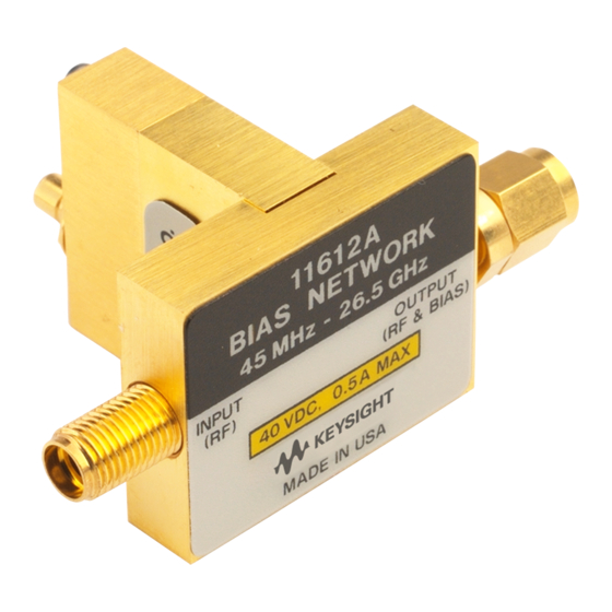
- Page 1 Keysight 11612A Bias Network Includes Option 001 Serial Numbers: This manual applies directly to Keysight 11612A Bias Networks with serial number prefix 2301A and higher. Operating and Service Manual...
-
Page 2: Safety Notices
WITH WARRANTY TERMS COVERING THE MATERIAL IN THIS documentation. No additional DOCUMENT THAT CONFLICT WITH government requirements © Keysight Technologies, Inc. THESE TERMS, THE WARRANTY beyond those set forth in the 1989–2021 TERMS IN THE SEPARATE EULA shall apply, except to the AGREEMENT WILL CONTROL. - Page 3 Keysight Technologies 11612A Bias Network Operation and Service Manual 11612A Bias Network In the following graphic, all dimensions are in millimeters. Figure 1 11612A Dimensions...
-
Page 4: General Information
“Contacting Keysight” on page Preparation For Use Interconnections The 11612A bias network is connected in line with the device to be biased. The bias is applied through the SMB snap-on connector. Refer to Figure 3 on page 6. A BNC to SMB adapter cable (part number 5062-4550) is also included in the 11612A bias network assembly. - Page 5 12.4 to 26.5 GHz 1.3 dB Maximum Bias Current 500 mA Maximum Bias Voltage ±40 V 11612A Option 001 Specifications 0.4 to 26.5 GHz Frequency Range Return Loss (both ports) – Minimum 0.045 to 1 GHz 14 dB 1 to 18 GHz 18 dB 18 to 26.5 GHz...
-
Page 6: Supplemental Characteristics
The electrical performance of the bias network is independent of its pin depth within the range stated above. b. 3.5 mm connectors mate with SMA connectors. 11612A Option 001 Supplemental Characteristics 0.000 to 0.127 mm (0.0000 to 0.0050 inches) -
Page 7: Operation
Figure 2 Bias Network Schematic Diagram Figure 3 shows the 11612A bias network connected in a typical measurement setup. Although other applications are possible, the general method of setup and operation is the same. Operation and Service Manual 11612-90001... - Page 8 The following procedure sets the correct power levels for the bias network when you’re using it for pulsed measurements. This procedure applies only to the 11612A option 001 high current bias network and should not be used with the standard 11612A.
-
Page 9: Storage And Shipment
95% Altitude up to 7,625 meters (25,000 feet), mean sea level Returning a Device to Keysight If your device requires service, contact Keysight Technologies for information on where to send it. See “Contacting Keysight” on page 11. Include the following information: —... -
Page 10: Performance Tests
1. Connect the equipment for a standard reflection measurement. 2. Calibrate the system with an open and a short. 3. Connect the appropriate RF port of the 11612A to the network analyzer test port. Terminate the opposite port with a 50 ohm load. - Page 11 11612A Bias Network Table 4-1 Performance Test Record Standard 11612A 11612A Option 001 Measured Value Return Loss Input Port Input Port 0.045 to 8 GHz 0.4 to 1 GHz 8 to 18 GHz 1 to 18 GHz 18 to 26.5 GHz 18 to 26.5 GHz...
- Page 12 11612A Bias Network Figure 5 11612A Option 001 Duty Cycle Curves, Overall View Operation and Service Manual 11612-90001...
-
Page 13: Contacting Keysight
11612A Bias Network Figure 5-1 11612A Option 001 Duty Cycle Curves, Overall View Contacting Keysight Assistance with test and measurement needs and information on finding a local Keysight office are available on the Web at: www.keysight.com/find/assist In any correspondence or telephone conversation, refer to the Keysight product by its model number and full serial number. - Page 14 11612A Bias Network Operation and Service Manual 11612-90001...
- Page 15 Installation Note Xxxxx-xxxxx...
- Page 16 This information is subject to change without notice. © Keysight Technologies 1989-2021 Edition 1, August 2021 www.keysight.com...
Need help?
Do you have a question about the 11612A and is the answer not in the manual?
Questions and answers