Table of Contents
Advertisement
Quick Links
OPERATING CONDITIONS
--- Medium: water
--- Water inlet temperature: from 6 to 45 °C
--- Max. air outlet temperature: 40 C
--- Max. operating pressure: 8 bar
--- Power supply: 230 V 50 Hz AC
--- Maximum relative humidity in the environment: 60%
ADVANTAGES
--- High energy efficiency
--- High performance (compensation of high thermal loads)
--- Low noise level
--- Compact dimensions and low mounting height
--- Low mounting and maintenance expenditure
--- Decentral air conditioning
SCHAKO | Ferdinand Schad KG
Steigstraße 25-27
D-78600 Kolbingen
TECHNICAL DOCUMENTATION
PERFORMANCE DATA
V
=
L
p
=
s
W =
Q =
Q
=
T
Q
=
S
Heating: t
= 45 °C, t
= 40 °C, t
= 20 °C
W1
W2
R
Cooling: t
= 7 °C, t
= 12 °C, t
= 27 °C, HR = 47 %
W1
W2
R
Technical data for the standard model according to (EU) 2016/2281
for product 3, 4-pipe model with ISO Coarse 50% filter at the point of
maximum static performance.
INTENDED USE
Intended use as fan coil unit according to Commission
Regulation (EU) 2016/2281 of 30 November 2016
Phone +49 (0) 7463-980-0
Fax +49 (0) 7463-980-200
www.SCHAKO.de | info@SCHAKO.de
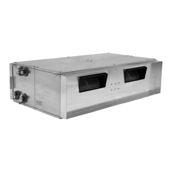
NBS
Fan coil unit
NBS-100-3
NBS-150-3
1360 m³/h
3529 m³/h
135 Pa
225 Pa
274 W
1300 W
7.21 kW
16.04 kW
9.63 kW
22.15 kW
7.04 kW
16.60 kW
Advertisement
Table of Contents

Related Manuals for Schako NBS Series


Summary of Contents for Schako NBS Series
- Page 1 Regulation (EU) 2016/2281 of 30 November 2016 --- Low noise level --- Compact dimensions and low mounting height --- Low mounting and maintenance expenditure --- Decentral air conditioning SCHAKO | Ferdinand Schad KG Phone +49 (0) 7463-980-0 Steigstraße 25-27 Fax +49 (0) 7463-980-200 D-78600 Kolbingen...
-
Page 2: Table Of Contents
NBS – Fan coil unit TECHNICAL DOCUMENTATION Contents CONTENTS General description ................................3 Device description ................................3 Models, dimensions and weights ............................5 Air filter ....................................6 Flange ....................................7 Position of the hydraulic connections ..........................8 Droplet separator ................................9 Mixing unit .................................. -
Page 3: General Description
NBS – Fan coil unit TECHNICAL DOCUMENTATION General description | Device description GENERAL DESCRIPTION DEVICE DESCRIPTION NBS room air conditioning modules are units with small mounting height for decentralised air treatment. They are MODELS particularly suitable for small units in which higher cooling capacities and pressures are required than those that a NBS-…... - Page 4 NBS – Fan coil unit TECHNICAL DOCUMENTATION Device description STANDARD MODEL PRODUCT NBS-100 STANDARD MODEL PRODUCT NBS-150 1 Housing 1 Housing --- Galvanised sheet steel profiles. --- Aluminium profiles. --- Galvanised sheet steel with a thickness of 1 mm. --- Galvanised sheet steel with a thickness of 1 mm. --- Sound and thermal insulation of 12 mm.
-
Page 5: Models, Dimensions And Weights
NBS – Fan coil unit TECHNICAL DOCUMENTATION Models, dimensions and weights MODELS, DIMENSIONS AND WEIGHTS NBS-100 NBS-150 Weights (kg) Weights (kg) Water Water Model Model (mm) (mm) -100-1 18.5 1.89 0.89 -150-1 3.50 1.73 -100-2 1150 24.0 3.39 1.69 -150-2 1374 5.82 2.97... -
Page 6: Air Filter
-100-3 1656x148x10 552x295x10 out sideways or optionally also downwards or upwards. To facilitate filter removal, SCHAKO offers a divided filter. -150-1 796 x 198 x 10 398x395x10 -150-2 1294x198x10... -
Page 7: Flange
NBS – Fan coil unit TECHNICAL DOCUMENTATION Flange FLANGE Dimensions The units are connected to the air ducts by means of a flange. Flange NBS-100 F0 = without flange (standard) FZ = with supply air flange FA = with return air flange FB = with supply air and return air flange Supply air flange... -
Page 8: Position Of The Hydraulic Connections
NBS – Fan coil unit TECHNICAL DOCUMENTATION Position of the hydraulic connections POSITION OF THE HYDRAULIC CONNECTIONS Installation W1 = In air flow direction on the left (standard) Air vent Cooling water outlet Heating water outlet Heating water inlet Cooling water inlet W2 = In air flow direction on the right Cooling water outlet... -
Page 9: Droplet Separator
NBS – Fan coil unit TECHNICAL DOCUMENTATION Droplet separator | Mixing unit DROPLET SEPARATOR The droplet separator consists of polypropylene leaves and a NOTE rack made of galvanised or stainless sheet steel. According to the Regulation (EU) 2016/2281, the admissible external air proportion (ODA) is <10% of the total air volume T0 = without droplet separator (standard) -
Page 10: Flexible Connections
NBS – Fan coil unit TECHNICAL DOCUMENTATION Flexible connections FLEXIBLE CONNECTIONS Dimensions NOTE Flexible connections NBS-100 Flexible connection is ordered and supplied separately. The unit is connected to the air ducts by means of a flexible connection to avoid the transmission of vibration to the duct. Z1 = 150 mm for supply air Z2 =... -
Page 11: Supply Air And Return Air Boxes
NBS – Fan coil unit TECHNICAL DOCUMENTATION Supply air and return air boxes SUPPLY AIR AND RETURN AIR BOXES Insulations NOTE The boxes consist of galvanised sheet steel and are lined with Plenum box is ordered and supplied separately. sound and heat insulation. The following insulations are possible: NOTE To connect the plenum box to NBS, the NBS must be... - Page 12 NBS – Fan coil unit TECHNICAL DOCUMENTATION Supply air and return air boxes Connection type Connection in air flow direction M00 = Connection closed In air flow direction MAB = Connection open (supply air) MRE = Connecting flange right M1x = with x spigots DN123 M2x = with x spigots DN158...
- Page 13 NBS – Fan coil unit TECHNICAL DOCUMENTATION Supply air and return air boxes Dimensions with connection open NBS-100 Number Model (mm) (mm) of bores X -100-1 -100-2 1232 -100-3 1742 NBS-150 Number Model (mm) (mm) of bores Y -150-1 -150-2 1380 -150-3 1830...
- Page 14 NBS – Fan coil unit TECHNICAL DOCUMENTATION Supply air and return air boxes Connecting flange dimensions NBS-100 Number Model (mm) (mm) of bores X -100-1 -100-2 1232 -100-3 1742 NBS-150 Number Model (mm) (mm) of bores Y -150-1 -150-2 1380 -150-3 1830 Construction subject to change.
- Page 15 NBS – Fan coil unit TECHNICAL DOCUMENTATION Supply air and return air boxes Spigot dimensions NBS-100 n = number of spigots Number Model (mm) (mm) of bores X -100-1 -100-2 1232 -100-3 1742 NBS-150 n = number of spigots Number Model (mm) (mm)
- Page 16 NBS – Fan coil unit TECHNICAL DOCUMENTATION Supply air and return air boxes Spigot dimensions NBS-100 n = number of spigots Number Model (mm) (mm) of bores X -100-1 -100-2 1232 -100-3 1742 NBS-150 n = number of spigots Number Model (mm) (mm)
-
Page 17: Silencer
Dimensions Silencing baffles Baffle silencer Due to their device-related design, the baffle distance and total length, SCHAKO's silencers provide an optimum silencing value while ensuring minimum pressure loss. NOTE The technical data of the ZMWS-NBS can be found directly in the MWS documentation or SCHAKO's selection programme. -
Page 18: Accessories
G 1 ¼ 260 - 1670 280 - 1800 1.- The volumetric flow [l/h] can be found in the technical 468 - 3400 documentation or in the SCHAKO design program. VC14 VPP46.32F4Q G 1 ½ 510 - 3700 2.- Selection of the optimum valve. The valve must be 550 - 4001 operated at approx. - Page 19 NBS – Fan coil unit TECHNICAL DOCUMENTATION Accessories 6-WAY BALL VALVE ROTARY DRIVE FOR 6-WAY BALL VALVE Adapter Code Model Type Signal Code Model left right 2 pos.; AR01 GDB341.9E AC 100…240 V ~ (m³/h) (m³/h) 15 20 25 switchover ✓...
- Page 20 NBS – Fan coil unit TECHNICAL DOCUMENTATION Accessories ROOM THERMOSTAT Operation RDG100, RDG110, A room thermostat can be used both to actuate the actuators RDG100T, RDG160T and to control the fans. RDG100KN, RDG160KN Control outputs ✓ TR01 RDG100 ✓ TR02 RDG100T AC 230 V ✓...
-
Page 21: Installation
Check whether the condensate pan is completely emptied by Condensate drain Ø16 mm partly filling it. NOTE SCHAKO recommends installing vibration-damping fixing elements to avoid structure-borne noise transmission. NOTE The rods, screws or vibration damping fixing elements required for installation are not included in the delivery. -
Page 22: Maintenance
If no differential pressure gauge is available, the filter should be replaced when it is full (dark filter mat). SCHAKO recommends purchasing replacement filters to avoid prolonged downtimes during maintenance activities. -
Page 23: Circuit Diagrams
NBS – Fan coil unit TECHNICAL DOCUMENTATION Circuit diagrams NOTE CIRCUIT DIAGRAMS Type NBS-100 is delivered with prewired speeds v1, v3 and v5, if no other data are given on the order. On-site modifica- tion possible! NBS-100-1 -20°C < air temperature range < +40°C NBS-100-2 -20°C <... - Page 24 NBS – Fan coil unit TECHNICAL DOCUMENTATION Circuit diagrams NBS-150-1 -20°C < air temperature range < +40°C NBS-150-2 -20°C < air temperature range < +40°C Construction subject to change. No return possible. Version: 06.05.21 | Page 24...
- Page 25 NBS – Fan coil unit TECHNICAL DOCUMENTATION Circuit diagrams NBS-150-3 -20°C < air temperature range < +40°C Operating conditions Model -100-1 -100-2 -100-3 -150-1 -150-2 -150-3 Supply voltage 230 V AC, 50/60 Hz single-phase 230 V AC, 50 Hz single-phase Type of insulation Type B Type B...
-
Page 26: Technical Data
NBS – Fan coil unit TECHNICAL DOCUMENTATION Technical data TECHNICAL DATA NBS-100-1-L4-C5 Δp Δp motor (m³/h) (Pa) (kW) (kW) (l/h) (kPa) (°C) (l/h) (kW) (l/h) (kPa) (°C) 2.52 1.82 10.4 1.87 36.6 2.39 1.72 10.3 1.77 36.8 2.17 1.55 10.0 1.62 37.2 s, max... - Page 27 NBS – Fan coil unit TECHNICAL DOCUMENTATION Technical data NBS-100-2-L4-C5 Δp Δp motor (m³/h) (Pa) (kW) (kW) (l/h) (kPa) (°C) (l/h) (kW) (l/h) (kPa) (°C) 4.83 3.46 10.2 3.48 36.5 4.35 3.10 10.0 3.16 36.9 3.72 2.64 2.72 37.5 s, max 2.89 2.04 2.15...
- Page 28 NBS – Fan coil unit TECHNICAL DOCUMENTATION Technical data NBS-100-3-L4-C5 Δp Δp motor (m³/h) (Pa) (kW) (kW) (l/h) (kPa) (°C) (l/h) (kW) (l/h) (kPa) (°C) 6.98 4.99 1202 10.1 5.33 37.5 6.59 4.70 1134 10.0 5.05 37.8 6.10 4.34 1051 4.70 38.2 s, max...
- Page 29 NBS – Fan coil unit TECHNICAL DOCUMENTATION Technical data NBS-150-1-L4-C5 Δp Δp motor (m³/h) (Pa) (kW) (kW) (l/h) (kPa) (°C) (l/h) (kW) (l/h) (kPa) (°C) 1045 7.27 5.32 1252 27.4 11.4 5.08 14.9 34.5 6.79 4.94 1169 24.2 11.2 4.75 13.2 34.9 s, max...
- Page 30 NBS – Fan coil unit TECHNICAL DOCUMENTATION Technical data NBS-150-2-L4-C5 Δp Δp motor (m³/h) (Pa) (kW) (kW) (l/h) (kPa) (°C) (l/h) (kW) (l/h) (kPa) (°C) 1423 10.40 7.52 1790 15.6 10.8 7.38 1260 12.1 35.5 1329 9.86 7.11 1697 14.2 10.6 7.01 1197...
- Page 31 NBS – Fan coil unit TECHNICAL DOCUMENTATION Technical data NBS-150-3-L4-C5 Δp Δp motor (m³/h) (Pa) (kW) (kW) (l/h) (kPa) (°C) (l/h) (kW) (l/h) (kPa) (°C) 2160 1165 15.47 11.25 2663 20.6 11.1 11.39 1945 18.1 35.7 2024 14.70 10.65 2531 18.8 10.9 10.86...
- Page 32 NBS – Fan coil unit TECHNICAL DOCUMENTATION Technical data SOUND POWER LEVEL (dB) Model 63 Hz 125 Hz 250 Hz 500 Hz 1000 Hz 2000 Hz 4000 Hz 8000 Hz (dB(A)) motor NBS-100-1 NBS-100-2 NBS-100-3 NBS-150-1 NBS-150-2 NBS-150-3 Sound power level measured at max. motor speed, free throw. The sound power level is reduced in case of duct mounting.
-
Page 33: Legend
NBS – Fan coil unit TECHNICAL DOCUMENTATION Legend LEGEND (mm) Width (mm) Height (mm) Length (mm) Diameter, nominal width Relative humidity in the room Δp (kPa) Water pressure loss in the heat exchanger (Pa) Available static pressure (kW) Thermal capacity (kW) Sensible capacity (kW) -
Page 34: Order Code Nbs
NBS – Fan coil unit TECHNICAL DOCUMENTATION Order code NBS ORDER CODE NBS Type Model Size System Air filter Filter removal Flange Example -100 Water Droplet Mixing unit connection separator position Example NOTE Please always specify the complete order code in the order! If details are missing from the order, the standard model will be delivered. -
Page 35: Order Code Fa-Nbs
NBS – Fan coil unit TECHNICAL DOCUMENTATION Order code FA-NBS ORDER CODE FA-NBS Type Family Model Size Model Example -NBS -100 NOTE Please always specify the complete order code in the order! If details are missing from the order, the standard model will be delivered. Any special model not included in the order code must be queried before ordering. -
Page 36: Order Code Pl-Nbs
NBS – Fan coil unit TECHNICAL DOCUMENTATION Order code PL-NBS ORDER CODE PL-NBS Type Family Model Size Model Length Insulation Example -NBS -100 -0500 Connection in Connection in air Connection in air air flow flow direction on flow direction on direction the left the right... -
Page 37: Order Code Zmws-Nbs
NBS – Fan coil unit TECHNICAL DOCUMENTATION Order code ZMWS-NBS ORDER CODE ZMWS-NBS Type Family Model Size Model Length Baffle thickness Example ZMWS -NBS -100 -1000 -100 Number of baffles Example NOTE Please always specify the complete order code in the order! If details are missing from the order, the standard model will be delivered. -
Page 38: Order Code For Lwz Accessories
NBS – Fan coil unit TECHNICAL DOCUMENTATION Order code for LWZ accessories ORDER CODE FOR LWZ ACCESSORIES Type Model Example -VC03 NOTE Please always specify the complete order code in the order! If details are missing from the order, the standard model will be delivered. Any special model not included in the order code must be queried before ordering. -
Page 39: Specification Text
Models for operation with circulating air only or a mixture of with droplet separator with polypropylene blades and a rack processed fresh air and circulating air! made of stainless sheet steel Manufacturer: SCHAKO Mixing unit Family: room air conditioning module NBS... - Page 40 NBS – Fan coil unit TECHNICAL DOCUMENTATION Specification text PL-NBS (plenum box for NBS) Plenum box made of galvanised sheet steel Connection in air flow direction on the right connection closed in air flow direction on the right -R00 Type connection with x spigot DN123 in air flow direction on the plenum box right -R1x...
- Page 41 NBS – Fan coil unit TECHNICAL DOCUMENTATION Specification text Accessories Pressure independent control valves 6-way ball valve VPP46.10L0.2 -VC01 VWG41.10-0.25-0.40 -V601 VPP46.10L0.4 -VC02 VWG41.10-0.25-0.65 -V602 VPP46.15L0.2 -VC03 VWG41.10-0.25-1.00 -V603 VPP46.15L0.6 -VC04 VWG41.10-0.40-0.65 -V604 VPP46.20F1.4 -VC05 VWG41.10-0.40-1.00 -V605 VPP46.25F1.8 -VC06 VWG41.10-0.40-1.30 -V606 VPP46.32F4.0 -VC07...
Need help?
Do you have a question about the NBS Series and is the answer not in the manual?
Questions and answers