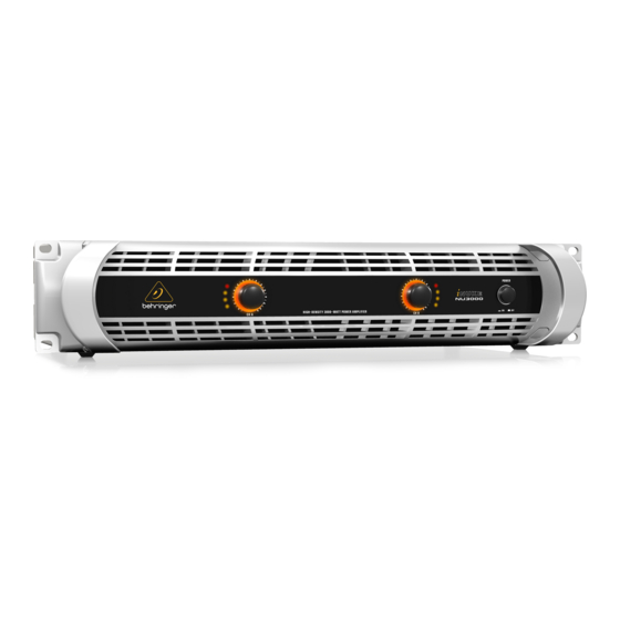
Behringer iNUKE NU3000 Quick Start Manual
Hide thumbs
Also See for iNUKE NU3000:
- Quick start manual (20 pages) ,
- Features (11 pages) ,
- Overview (6 pages)
Advertisement
Quick Links
Project:
Model:
Materials:
This rework must only be performed by a qualified technician.
To reduce the risk of death or injury be sure to observe all correct safety procedures.
1. When replacing T1 & T5 from MOSFET to IGBT it is suggested that the following components also be checked and
replaced as needed. D5, D12, R9, R10, R11, R17, R21, R25, T2, T3.
D5, D12
(DIODE;SCHOTTKY;SS0540;SOD123;SMD;ROHS)
R9, R25
(10k)
R10, R21
(10ohm)
R11, R17
(1k)
T2, T3
(TRANSISTOR;MMBT4403;SOT23;ROHS)
P0AHN
NU3000
Soldering Iron, Solder Paste.
Components: 2 x T-IRGB-20B60PD1 (S.SKU Z74-53206-04503)
C10-18700-5408
J73-16440-36603
Advertisement

Subscribe to Our Youtube Channel
Summary of Contents for Behringer iNUKE NU3000
- Page 1 Project: P0AHN Model: NU3000 Materials: Soldering Iron, Solder Paste. Components: 2 x T-IRGB-20B60PD1 (S.SKU Z74-53206-04503) This rework must only be performed by a qualified technician. To reduce the risk of death or injury be sure to observe all correct safety procedures. 1.
- Page 2 2. Locate FETS in position T1 & T5. 3. Remove FETS then remove the heatsinks. Legs first, FET, then Heatsink. 4. Clean solder off PCB. ...
- Page 3 5. T1 & T5 should look like this when flux is remove leaving a flat surface. 6. Place solder paste on small square on PCB and also on rear of new IGBT FET. 7. Place FET on PCB and solder feet into position to secure. New FET is T‐IRGB‐20B60PD1 (S.SKU Z74‐53206‐04503) ...
- Page 4 8. Apply pressure with soldering iron to FET allowing solder paste to heat up. FET should now be firmly in place. Apply pressure here. Confirm solder has melted around inner circle and around edges. This needs to really be done with a large tip iron and medium temperate for no longer than 10 seconds. 9. Same again for other FET. ...
- Page 5 10. Both FETS are now firmly in place, assuring flat surface on PCB. 11. Place heatsinks back on the PCB (with solder paste between heatsink and PCB) and solder into place. Easy to work here with heatsink bent upwards. 12. Test all functions and assemble. ...


Need help?
Do you have a question about the iNUKE NU3000 and is the answer not in the manual?
Questions and answers