Table of Contents
Advertisement
Quick Links
Advertisement
Table of Contents

Related Manuals for HOLYKELL 4800E


Summary of Contents for HOLYKELL 4800E
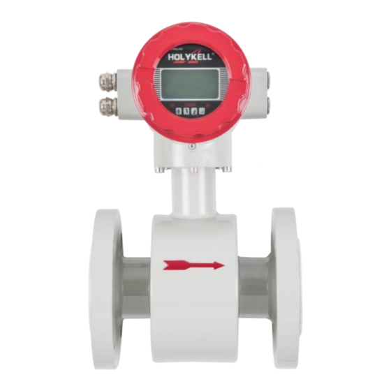
- Page 1 ELECTROMAGNETIC FLOW METER USER MANUAL 4800E 4800 4800E 4880E...
-
Page 2: Table Of Contents
Contents Product description..........................1 Working principle..........................1 Features..............................1 Technical parameter..........................2 Flange connection structure and installation dimensions..............5 Flow range table..........................6 Instrument installation......................... 7 Installation location selection......................7 Installation requirements........................7 Electromagnetic Flow meter Converter Instruction Manual............9 The product function introduction....................9 Basic circuit of converter...................... -
Page 3: Product Description
Product description Smart electromagnetic flow meter is a high-performance, high-reliability flow meter. It used to measure the volume flow of conductive liquid and slurry in closed pipelines. Widely used in steel, electricity, petroleum, chemical industry, coal, metallurgy, papermaking, water supply and drainage, food, pharmaceutical industry, etc. -
Page 4: Technical Parameter
Technical parameter Item Technical parameter Main power AC220V 50HZ/DC24V/DC12V/3.3V battery power supply Power consumption <15W (Supporting power consumption with sensors ) Display in Chinese and English, can display instantaneous flow, accumulated flow Display and buttons and alarm display (excitation open circuit alarm, empty pipe alarm, flow over limit alarm). - Page 5 Model Code Selection Table: Code No. Meter Type 4800 Segregate Type Electromagnetic Flow Meter, 4800E Integrated Type Electromagnetic Flow Meter 4880 Sanitary Segregate Type Electromagnetic Flow Sensor 4880E Sanitary Type Integrated Electromagnetic Flow Meter Code No. Nominal Diameter 4800 4800E...
- Page 6 Explosion proof ○ ● ○ ● type( 24v.DC) Selection codes explanation Model Code: 4800E50DY3MX5B1F1P1RE-L 4800E Type Diameter Supply Pressure Output Lining Electrode Housing Grade Ground Explore Max Proof Flow Note: "●" on behalf of optional," ○" is mean not optional.
-
Page 7: Flange Connection Structure And Installation Dimensions
Flange connection structure and installation dimensions Unit: mm L(PTFE) L(Rubber/PFA/F46) n*d0 4*14 4*14 4*14 4*14 4*18 4*18 4*18 4*18 8*18 8*18 8*18 8*23 12*23 12*26 12*26 16*23 16*26 20*26 20*26 20*25 24*25 24*30 1075 1020 24*30 1000 1000 1175 1120 28*30 1200 1190... -
Page 8: Flow Range Table
Flow range table Flow range and Flow rate table m3/h 15(maximum) 0.14 0.28 0.27 0.85 1.13 1.41 4.24 0.14 0.28 0.27 0.85 1.13 1.41 4.24 0.32 0.64 1.27 1.91 2.54 3.18 9.54 0.57 1.13 2.26 3.39 4.52 5.65 16.96 0.88 1.77 3.53 5.30... -
Page 9: Instrument Installation
Instrument installation Choosing the correct installation location and adopting the correct installation method is the key to using the electromagnetic flow meter. If the installation is wrong, Not only will it affect the measurement effect, it will also affect the measurement accuracy, it will also affect the life of the flow meter, and even damage the flow meter. - Page 10 3. Instrument wiring ● If the signal cable connected by split installation uses a customized dedicated cable, the shorter the cable, the better. ● The excitation cable can choose Yz medium-sized rubber sheathed cable, and its length is the same as the signal cable.
-
Page 11: Electromagnetic Flow Meter Converter Instruction Manual
Electromagnetic Flow meter Converter Instruction Manual The product function introduction Basic function ● Low-frequency square-wave exciting,exciting frequency:1/16 power frequency,1/20power frequency,1/25 power frequency; ● High-frequency square-wave exciting ,exciting frequency:1/2 power frequency (for grouting liquid measure); ● Exciting current can be selected for 125mA,187.5mA,250mA,500mA; ●... - Page 12 Type of connecting with sensors ● The integrated Circular shells: Circular shells, shells connect with the flange directly, explosion-proof; ● The integrated squared shells: squared shells, shells connect with the flange directly; ● The split squared shells: squared shells (hang on the wall), Signal converters connect with cable of sensor; Plot of installing measure Fig.1 Exterior size of the integrated Circular shells Fig.2...
-
Page 13: Basic Circuit Of Converter
Basic circuit of converter 32 bit preampli fier exciting circuit EEROM 85~260V Switching Display 45~63Hz Power Supply 4-20mA or Keyboard Current Output 0-10mA 1-5000Hz Frequency or Pulse Output Pulse Output Status OC Gate Status Control Output Communication RS485 .etc Interface Fig.2. - Page 14 3.2.2 Request of relative sensor Sensitivity of sensor signal: under 1m/s, output 150µV ~200µV; For electromagnetic flow meter signal converters, there are four currents of 62.5mA in exciting loop, which make up of 250mA, and every 62.5mA is controlled by one 20Ω exact resistance. So user can choose different exciting current by changing the number of exact resistance.
- Page 15 3.2.5 Digital frequency output Frequency output range: 1~5000Hz; Output electric isolate: Photoelectric isolate. Isolate voltage: > 1000VDC; Frequency output drive: output by field-effect transistors, the highest subjected voltage is 36VDC , maximum of output current is 250mA. 3.2.6 Digital pulse output Pulse output range: 0 ~100 pulse/s.
-
Page 16: Transmitter Operation
Insulated voltage between alarm output and AC power supply should be higher than 500V; Insulated voltage between alarm output and earth should be higher than 500V; Transmitter operation Key and display 4.1.1 Squared define keys and LCD screen display Fig. 4.1 (c) Keys on squared panel and large LCD display: 4.1.2 Rotundity define keys and LCD screen display Fig. - Page 17 Note: When measuring, pushing down “Compound Key + Enter” will appear password of changing state, base on distinction of secrecy, and change the password as we provide. Then pushing “Compound Key + Enter” again, and you can inter the state of setting parameter. If want to return to the running state, push “Enter”...
- Page 18 Labels of connectors in squared model 4.3.2 Signal lines and labels in squared model Fig.4.3 (b) Connection and labels of signal lines in squad model 4.3.3 Links and labels of connectors in Circular Model...
- Page 19 COM I+ COM P+ AH AL L2 L1 FUSE T+ G Fig.4.3(c) Connectors in circular model Symbols and Description of Connectors in Circular Pane I+: Output Current for Flow Measurement COM: Output Current (Ground) for Flow Measurement Frequency(Pulse) Output for Bi-directional Flow P+:...
- Page 20 Fig.4.3 (d) Labels and connection of signal lines in Circular model Signal lines labels in Circular model: White twisted-pair cable (for exciting current): 12 Conductors (Red) 12 Conductors (Black) Gray shielded twisted-pair cable: 10 Conductors (Red) connected to “Signals 1” 13 Conductors (White) connected to “Signals 2”...
- Page 21 Suggested model is RVVP2*0.3 mm . Length of exciting current cable should be equal to that of signal cable. When the model STT3200 cables are used for exciting current and signals, two cables can be put together as one cable. 4.4.3 Output and power line All cables for signals transferring and power supply must be prepared by users.
- Page 22 Fig.4.4 (c) Connection of electronic counter Fig.4.4 (d) Connection of alarm output Fig.4.4(e)Connection of OC gate 4.4.4 The grounding requirements when installing convert Contact area of copper Connector PE on Converter Cabinet for grounding should be larger than 1.6mm .Contact resistance should be less than 10Ω.
- Page 23 First, purple copper tube should be cut into 1700 mm long (the copper tube can be lengthened according to the need ) to make the nail buried 1500 mm into the ground(Note : when burying nail, sprinkling a layer of broken charcoal at the top of nail, and then saline irrigation). Then, 4 mm2 purple copper wire should be welded to the nail.
- Page 24 The up limit of frequency output can be adjusted. It can be chosen from 0 ~ 5000HZ, and also can be chosen low frequency: such as 0 ~ 1000HZ or 0 ~ 5000HZ. Frequency output mode general can be used in control application, because it responses the percent flux. Users can choose pulse output when the equipment is applied to count.
- Page 25 Pout User equipment Voltage input Pcom Inside Fig.4.5(a) The connection of digital voltage output 4.5.5 Digital output connect photoelectricity coupling (PLC etc.) Fig.4.5(b) Digital output connect photoelectricity coupling Commonly user’s photoelectricity coupling current is about 10mA, so about E/R=10mA, E=5~24V. 4.5.6 Digital output connect relay Pout inside...
- Page 26 IC=100mA Frequency 5000 Vcc=24V High voltage IC=100mA Low voltage IC=100mA Simulation signal output and calculate 4.6.1Simulation signal output Simulation signal output inner is 24V under4~20mA, it can drive 750Ω resistance. The percent flux of simulation signal output: Measure value ● the scale of current + the zero point of current Full scale value The current zero is 4mA when 4~20mA.
- Page 27 Adjust the current zero and the full range, the current function of the converter reached exactness. The line degree of current output of conversion should be controlled within the scope of 0.1% (4)Current line degree checking You can place the standard signal source in 75%,50%,25%,and check the line degree of current output. 4.6.3 Electromagnetic flow meter converter’s connection of current output:...
-
Page 28: Setting Parameters
5. Setting parameters 5.1 After electromagnetic flow meter converter and sensor connect to the pipe (no matter demarcate or use), may do the next work first: Connect the pipe fore-and-aft the sensors tighten. Make sure the sensor connects the earth. ... - Page 29 (3) Direct select of zero correction about the flow, you can move the cursor to the left + or - , and use “Down” or “Up” to switch; 5.2.2 Function keys for setting parameters To set or correct working parameters, the converter should be running in parameters setting way instead of measuring status.
- Page 30 Modif Rec”(Detail consult the AppendixFive) 5.2.4 Setting Parameters in Menu There are 55 parameters of , user can set every parameter. The List of Parameters is shown below: Setting Parameters in Menu Code Parameter words Setting Way Grades Range Language Select English Comm Addres...
- Page 31 Alm Hi Val Set count 000.0~ 599.99 % Alm Lo Ena Select Enable/Disable 000.0~599.99 % Alm Lo Val Set count Sys Alm Ena Select Enable/Disable Clr Sum Key Set count 0~99999 Snsr Code1 User set Finished Y M Snsr Code2 User set Product number Field Type...
- Page 32 Pass Word 4 User correct 00000~99999 Analog Zero Set count 0.0000~1.9999 Anlg Range Set count 0.0000~3.9999 Meter Fact Set count 0.0000~5.9999 Meter Code 1 Factory set Finished Y /M Meter Code 2 Factory set Product Serial No No Parity/Odd Parity/Even Check Mode Select Parity...
- Page 33 The standard MODBUS communication for is 8 bit No Parity, users can choose 8 bit odd parity and 8 bit even parity according to the need. 5.3.5 Snsr Size Converters can be equipped with some deferent sensors that have deferent diameter of measuring pipes. The pipes in deferent diameters from 3mm to 3000mm can be chosen in relative table.
- Page 34 When FS is not “0”, make FS = 0. Note: if change the value on next line and FS increases, please change the “+, -” to correct FS to zero. Flow zero is the compound value of the sensor, and should be recorded in sensor list and band. The unit will be mm/s, and the sign will be opposite with correction value.
- Page 35 5.3.16 Pulse Fact Equivalent pulse Unit is referred to one pulse for value of flow. The range of pulse equivalent can be chosen: Pulse Equivalent Flow Pulse Equivalent Flow 0.001L/cp 0.001USG/cp 0.01L/cp 0.01 USG /cp 0.1L/cp 0.1 USG /cp 1.0L/cp 1.0 USG /cp 0.001m 0.001UKG/cp...
- Page 36 “Mtsnsr trip” that should be set. When setting “Mtsnsr trip”, you could be according to the real MTP, the value that should be set is usually three to five times of real MTP. 5.3.20 Alm Hi Ena Users can choose “Enable” or “Disable”. 5.3.21 Alm Hi Val The parameter of upper limit alarm is percentage of flow range and can be set in the way of setting one numerical value between 0%~199.9%.When the value of flow percentage is larger than the value of...
- Page 37 User use 5 byte code to enter, and can modify the positive accumulating volume (∑+). Usually, it is unsuitable to exceed the maximum the counter set(999999999). 5.3.29 RevTotal Lo,hi User use 5 byte code to enter, and can modify the negative accumulating volume (∑-). Usually, it is unsuitable to exceed the minimum the counter set(999999999).
-
Page 38: Infrared Telecontrol Function Keys
5.3.37 Meter Code 1 and 2 Converter code records the date of manufacturing and serial number of converter. 6. Infrared remote control function keys The operation of the infrared-hand-remote control keyboard is the same with the operation of the instrument. When use it, please keep the infrared transmitter of the infrared-hand-remote control keyboard and the receiver of the instrument parallel, with the distance of about one meter. - Page 39 No display: Check the power supply connection; Check the power fuse to see for OK; Check the contrast of LCD and regulate it to working state; Exciting alarm Check if the exciting cables EX1 and EX2 did not connected; Check if the total resistance of sensor’s exciting coil resistances less than 150Ω; If a) and b) are OK, the converter is failed.
-
Page 40: Encasement And Reserve
9. Encasement and reserve 9.1 Encasement Electromagnetic flow meter converter is packed as vacuum, and can insulate wet. The bag it’s appropriative one, if the bag is open, it will not product of original factory. Installation Manual, Certificate of Product and Packing List are all with the converter. 9.2 Shipping and storage To prevent the product from damage during shipping, keep the original package of manufacturer. - Page 41 Appendix One: Selection of exciting frequency(re.) Afford three exciting frequency types: 1/16 frequency (type 1), 1/20frequency (type 2), 1/25 frequency (type 3). The small-bore one should use 1/16 frequency, and large-bore one should use 1/20 or 1/25 frequency. When using, please select type 1 first, if the zero of velocity is too high, select the type 2 or type 3.
- Page 42 Exciting current transition time τ = L / R L ---- Exciting loop inductance; R ---- exciting loop resist. So decrease L and increase R both can decrease τ. According the analysis, change the connect of exciting loop, measure from either head of exciting loop, Total resist = (R1 + R ) parallel connection (R2 + R ) ≤...
- Page 43 Appendix Two: ON/OFF Switch Diagram Key 1: ON: Supply up power (24V) for ALML output. OFF: No connection. Key 2: ON: Pulse output to OC gate when flow verification was taken. Connect pull -up resistor. OFF: No connection. Key 3: ON: Supply up power (24V) for ALMH output.
- Page 44 Appendix Three: Analog Loop Communication function explaination Analog Loop Communication Bus network . Analog Loop Communication Bus transfers data-signal through signal line which value is from 4 to 20mA. Therefore, it can save local data communication line and implement data communication. Its adaptive for local using.
- Page 45 Appendix four: Lightning protection notes. When installing, users must connect the converter’s ground terminal with the shell, and then ground them reliably, because the electrical current can be put into the earth through the shell by the gas discharger of lightning protection. If the shell has not been ground reliably, once lightning, it may cause a personal accident when there is somebody operating the converter.
Need help?
Do you have a question about the 4800E and is the answer not in the manual?
Questions and answers