Table of Contents
Advertisement
Quick Links
Advertisement
Table of Contents

Subscribe to Our Youtube Channel
Related Manuals for ERL F-PRO 116


Summary of Contents for ERL F-PRO 116
- Page 1 Digitally signed by Norbert Wegner DN: cn=Norbert Wegner, o=ERLPhase Power Technologies Ltd., ou, email=nwegner@erlphase.com, c=CA Date: 2022.01.04 10:48:32 -06'00' F-PRO 116 Non-Directional Multifunction & SEF Protection Relay User Manual Version 1.2 Rev 0...
-
Page 3: Contact Information
Windows® is a registered trademark of the Microsoft Corporation. HyperTerminl® is a registered trademark of Hilgraeve. Modbus® is a registered trademark of Modicon. Contact Information ERLPhase Power Technologies Ltd., Website: www.erlphase.com Email: info@erlphase.com Technical Support Email: support@erlphase.com Tel: 1-204-477-0591 D05125R01.20 F-PRO 116 User Manual... -
Page 4: Using This Guide
Menu items and tabs are shown in italics. Service User input or keystrokes are shown in bold. Text boxes similar to this one Relate important notes and information. Indicates more screens. Indicates further drop-down menu, click to display list. Indicates a warning. F-PRO 116 User Manual D05125R01.20... -
Page 5: Table Of Contents
2.3 Power Supply................2.4 AC and DC Wiring..............2.5 Communication Wiring............. Setup and Communication 3.1 Power Supply ……………………..……………………………………………….. 3.2 USB Link …………………………………………………………………………….…. 3.3 Accessing the Relay’s SCADA Services ………………………………...… 3.4 Communication Port Details ………..……………………………………..… 3.5 Time Source.……………………………………........D05125R01.20 F-PRO 116 User Manual... - Page 6 Settings and Analysis Software 7.1 Offliner Setting Software ………………………………………………………. 7.2 Offliner Features ……………….………………………………………………….. 7.3 Offliner Keyboard Shortcuts …………….……………………………………. 7.4 Handling Backward Compatibility ………..…………………………….…. 7.5 Main Branches from the Tree View ………….………………………..…. Acceptance Test Guide 8.1 Acceptance Testing ……………………………………………………………….. F-PRO 116 User Manual D05125R01.20...
- Page 7 Appendix H Mechanical Drawings ……………………………………………….….………… H.1 Front View ………………………………….…………….……………..……………. H.2 Rear View ………………………………….…………….……………..…………….. Appendix I AC Schematic Drawing ……………………….…………………….…………… Appendix J DC Schematic Drawing …………………………………………….…………… Appendix K Connection Diagram……………………………….……………………………. Appendix L F-PRO Setting Example ………………………….………………………………. D05125R01.20 F-PRO 116 User Manual...
-
Page 8: Acronyms
- Data Communication Equipment - Human Machine Interface - International Electro-technical Commission - Intelligent Electronic Device - Light-emitting Diode - Liquid Crystal Display - Left Hand Side - Right Hand Side - Setting Group - User Interface F-PRO 116 User Manual D05125R01.20... -
Page 9: Version Compatibility
Offliner Settings are backward compatible with all earlier versions of setting files. F-PRO Firmware/Software Compatibility Guide Compatible Offliner Setting F-PRO Firmware Version Settings V1.2 V3.1 Please contact ERLPhase Technical support for complete Revision History. D05125R01.20 F-PRO 116 User Manual... -
Page 10: Pc System Requirements And Software Installation
• F-PRO Offliner: Software • USB STM32 – VCP Driver for F-PRO 116: Software (not required for Windows 10) • Relay User manual: Manual in PDF format To Install Software on the Computer To install the software on the computer, click the desired item on the screen. The installation program launches automatically. -
Page 11: Overview
IEEE and IEC inverse curves. Since the curves are equation-driven, the user can choose to enter equation parameters directly to create user defined overcurrent curve shapes as needed. To provide a complete package of protection and control, the F-PRO 116 provides other functions such as: •... - Page 12 Figure 1.1: F-PRO 116 Relay Function Line Diagram F-PRO 116 User Manual D05125R01.20...
-
Page 13: Front View
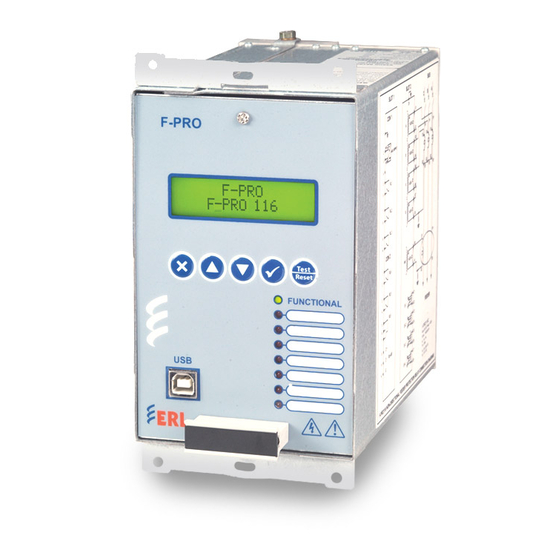
Front panel USB port provides easy and fast access to settings and set up Handle to draw out the relay from case. Figure 1.2: F-PRO Front View D05125R01.20 F-PRO 116 User Manual... -
Page 14: Rear View
1.3 Rear View Case Grounding RS-485 terminals for SCADA communication (MODBUS and IEC103) Figure 1.3: F-PRO Rear View F-PRO 116 User Manual D05125R01.20... -
Page 15: Model Options/Ordering
The external inputs are 24/30, 48/50, 110/125 or 220/250 Vdc rated. The Auxiliary supply is 20-60 Vdc or 80-300 Vdc rated. • All of the above options must be specified at the time of ordering. D05125R01.20 F-PRO 116 User Manual... - Page 16 Figure 1.4: Ordering Template F-PRO 116 User Manual D05125R01.20...
-
Page 17: Installation And Safety Instructions
2 Installation and Safety Instructions 2.1 Introduction This section deals with the installation of the F-PRO 116 when first delivered. The section covers the physical mounting, AC and DC wiring and the Communication wiring. The following symbols are used in this manual and on the unit. They should be understood before... -
Page 18: Power Supply
Shielded wire shall be used for all connections that run outside of the panel in which the F-PRO is installed. The shield must be grounded only at one end at the point where the cable enters the panel. F-PRO 116 User Manual D05125R01.20... - Page 19 COM 1 on the front panel is a standard USB-B connector. This port is the Maintenance port of the relay. This is a USB 2.0 Full Speed interface and can be connected to a PC with a standard USB peripheral cable (A style to B style). D05125R01.20 F-PRO 116 User Manual...
-
Page 21: Setup And Communication
The PC must be appropriately configured for USB communication. Connect to the IED via a USB cable connected COM1 on the front panel. COM1 is a USB-B interface. COM 1 - USB Laptop / PC Figure 3.1 USB Link D05125R01.20 F-PRO 116 User Manual... - Page 22 Now check the port in Device Manager: Start > Control Panel > Device Manager > Ports (COM & LPT) Find the "STM STLink Virtual" port and note COM port number which is installed (example: COM F-PRO 116 User Manual D05125R01.20...
-
Page 23: Accessing The Relay's Scada Services
SCADA protocol. “Modbus ASCII/ Modbus RTU/ IEC 60870-5-103/ DNP 3.0 Serial” uses 8 data bits and 1 stop bit. If used with parity (even or odd), there is one parity extra bit. D05125R01.20 F-PRO 116 User Manual... -
Page 24: Communication Port Details
Default Setting: 9600 N 8 1 (no parity, 8 data bits, 1 stop bit) Table 3.2: RS-485 Connections to Pins on Relay Port Signal Name Direction PC<-> Relay Pin # on the Relay Port SLOT 1, CON 2/8 SLOT 1, CON 2/9 SLOT 1, CON 2/A F-PRO 116 User Manual D05125R01.20... -
Page 25: Time Source
HyperTerminal will communicate with the F-PRO-116. After connecting the HyperTerminal, enter any key in the keyboard. The following Enter the USERNAME screen will appear as shown below: Enter the username “fpro”, the terminal automatically moves to the next step. D05125R01.20 F-PRO 116 User Manual... - Page 26 To set the relay’s time and date, enter the value 5. After the value 5 is entered in keyboard, the following will appear on the terminal screen. Enter A to Set Date in Format YYYY/MM/DD. Enter B to Set Time in Format HH/MM/SS. F-PRO 116 User Manual D05125R01.20...
- Page 27 Enter the Month (as a two-digit number). If a valid month is entered, date setting page will be appearing on the terminal screen. Enter the Date of Month (as a two digit number). D05125R01.20 F-PRO 116 User Manual...
- Page 28 Enter the Hour (as a two-digit number, in 24-hour format). If a valid hour value is entered, minute setting page will be appearing on the terminal screen. Enter minutes (as a two-digit number). If a valid minute value is entered, seconds setting page will be appear on the terminal screen. F-PRO 116 User Manual D05125R01.20...
- Page 29 Enter seconds (as a two-digit number). If a valid second value is entered, the time settings will get saved in the relay. After the hour, minute, second values were set in the terminal Enter E in the keyboard to exit to the main menu. D05125R01.20 F-PRO 116 User Manual...
-
Page 31: Using The Ied (Getting Started)
Front panel USB port provides easy and fast access to settings and set up Figure 4.1: Front Panel Display The LCD display, eight LED lights and five push buttons provide access to selective information about the relay. D05125R01.20 F-PRO 116 User Manual... - Page 32 To login into the LCD menu structure, follow these steps: F-PRO Bay Name Figure 4.2: Main Screen In the Main Screen, Press Enter Key. → View Change Service Figure 4.3: View / Change / Service: Choice Menu F-PRO 116 User Manual D05125R01.20...
- Page 33 Note: The default passwords are below: Access Level Password View No password for View access in LCD Change change Service service Password can contain “. = + - 0-9 a-z and A-Z”. The maximum number of allowed characters is 8. D05125R01.20 F-PRO 116 User Manual...
- Page 34 Fn. 50G-2 (V,C,S) Fn. 51G (V,C,S) (V,C,S) Fn. 64/50SEF-1 (V,C,S) Fn. 64/50SEF-2 (V,C,S) Fn. 64/51SEF (V,C,S) Neg.Seq.OC (V,C,S) Fn. 46/50 (V,C,S) Fn. 46/51 (V,C,S) Thermal Overload (V,C,S) Fn. 49 (V,C,S) CB Fail (V,C,S) Fn. 50BF (V,C,S) F-PRO 116 User Manual D05125R01.20...
- Page 35 (V,C,S) Analog (V,C,S) (V,C,S) Digital EI Status (V,C,S) DO Status (V,C,S) Records (V,C,S) View Events (V,C,S) View Faults (V,C,S) Utilities (V,C,S) Date & Time (V,C,S) Time (V,C,S) Date (V,C,S) Communication (V,C,S) USB(Serial) (V,C,S) (V,C,S) RS-485(CON2) D05125R01.20 F-PRO 116 User Manual...
- Page 36 PW Access Timer PW Enable / Disable Factory Update Test Mode Test Mode Selection Digital Output Control Unit Identifications (V,C,S) Where the access levels required to access each are indicated V: view C: change S: service F-PRO 116 User Manual D05125R01.20...
-
Page 37: Terminal Interface
HyperTerminal will communicate with the F-PRO-116. After connecting the HyperTerminal, enter any key in the keyboard. The following Enter the USERNAME screen will appear as shown below: Enter the username “fpro”, the terminal automatically moves to the next step. D05125R01.20 F-PRO 116 User Manual... - Page 38 Enter 3 for Collect/ Erase the stored Fault Log Data in the relay Enter 4 to get the configuration file from the relay Enter 5 to set RTC Date and Time Enter 6 for Firmware Update F-PRO 116 User Manual D05125R01.20...
- Page 39 After the terminal displays “Attach Your Configuration File” message: 1) From Transfer menu of HyperTerminal select ‘Send Text File’ option 2) Browse the appropriate folder where the configured setting file is located. 3) Select the configured text file and click open. D05125R01.20 F-PRO 116 User Manual...
- Page 40 After the configuration file got successfully loaded, the HyperTerminal shows the text “configuration File Successfully loaded”. The selected settings had been loaded and when the setting load is completed, an event is logged to show the completion of the request. 4-10 F-PRO 116 User Manual D05125R01.20...
- Page 41 Enter A to get Event Log data from the relay • Enter B to erase Event Log data from the relay • Enter E to exit the Get/Erase Event Log menu Figure 4.11: Get/ Erase Event Log Data D05125R01.20 F-PRO 116 User Manual 4-11...
- Page 42 4) Click Open 5) Enter the value A to get the Event Log 6) After the Events text is captured Select Capture text -> Stop 7) The events are now captured as a text file 4-12 F-PRO 116 User Manual D05125R01.20...
- Page 43 Enter A to get Fault Log data from the relay • Enter B to erase fault Log data from the relay • Enter E to exit the Get/Erase Fault Log menu Figure 4.14: Get/ Erase Fault Log Data D05125R01.20 F-PRO 116 User Manual 4-13...
- Page 44 Erase Fault Log To Erase Fault Log data from the relay, Enter the value B. After the fault logs got erased, the following text will appear on the terminal window ‘Fault Log Data Erased Successfully’ 4-14 F-PRO 116 User Manual D05125R01.20...
- Page 45 After the settings are captured select Capture text -> Stop under the transfer menu The Setting Configuration were captured as a text file Use F-PRO Offliner tool to edit or view the captured setting file D05125R01.20 F-PRO 116 User Manual 4-15...
- Page 46 Figure 4.18 Select Capture Text option from the Transfer Menu Figure 4.19: Browse for the path to save the configuration file 4-16 F-PRO 116 User Manual D05125R01.20...
- Page 47 After browsing for the desired file location, give a name to save the configuration file (in this example ‘FPRO1000’ given as the setting file name). Figure 4.21: Enter ‘A’ to get the setting configuration from the relay D05125R01.20 F-PRO 116 User Manual 4-17...
- Page 48 Figure 4.22: Select Stop Capture text option 5) Set RTC Date & Time Refer “3.5 Time Source” for set RTC in HyperTerminal. 6) Firmware Update Contact ERLPhase Power Technologies Ltd., for instructions on Firmware update. 4-18 F-PRO 116 User Manual D05125R01.20...
-
Page 49: Protection Functions And Specifications
5 Protection Functions and Specifications This section describes the equations and algorithms that are implemented in the F-PRO 116 relay Protection functions. The available functions are 50-1, 50-2, 51, 50N-1, 50N-2, 51N, 50G-1, 50G-2, 51G, 64/50SEF-1, 64/50SEF-2, 64/51SEF, 46/50, 46/51, 74TCS-1, 74TCS-2, 49, 50BF, 46BC, 81HBL2, 79. These functions are explained below with setting ranges and logic diagrams. - Page 50 0.0010 to 1000.0000 settable if chosen for user defined characteristics 0.0000 to 10.0000 settable if chosen for user defined characteristics 0.01 to 100.00 settable if chosen for user defined characteristics 0.10 to 150.00 settable if chosen for user defined characteristics Inrush Blocking Enable/disable F-PRO 116 User Manual D05125R01.20...
- Page 51 Phase Overcurrent Protection. User can define either 50N or 51N functions. User can apply inverse (51N), definite time (51N) and/or and instantaneous neutral Overcurrent protection (50N). Inverse time Function 51N provides selectable IEC or IEEE curves or user-defined curve. D05125R01.20 F-PRO 116 User Manual...
- Page 52 0.00 to 999.99 seconds Inrush Blocking Enable/disable 51N – IDMTL Derived Neutral Overcurrent Logic diagram Functional Block Via External Input Function Enable 51N Operated > 51N Pickup Inrush Block Figure 5.4: Logic Diagram of 51N Function F-PRO 116 User Manual D05125R01.20...
- Page 53 Inverse time Function 51G provides selectable IEC or IEEE curves or one user-defined curve. The definite time function (51G) is governed by the time delay set after the pickup of the function & the instantaneous overcurrent function (50G) has no time delay. D05125R01.20 F-PRO 116 User Manual...
- Page 54 0.00 to 999.99 seconds Inrush Blocking Enable/disable 51G – IDMTL Neutral Overcurrent Logic diagram Functional Block Via External Input Function Enable 51G Operated IG > 51G Pick up Inrush Block Figure 5.6: Logic Diagram of 51G Function F-PRO 116 User Manual D05125R01.20...
- Page 55 The sensitive earth fault protection, as the name suggests, is a highly sensitive function. It can sense currents as low as 0.5% of the CT secondary current. The sensitive earth fault relay may be configured to generate an alarm and / or a trip signal. D05125R01.20 F-PRO 116 User Manual...
- Page 56 Table 5.8: 64/50SEF Instantaneous SEF Settings (No. of Stages – 2) Setting Description Range Function Activation Enable/disable 0.005 to 3.000 A (1 A) / 0.025 to 15.000 A (5 A) Pickup ISEF>> Pickup Delay 0.00 to 999.99 seconds Inrush Blocking Enable/disable F-PRO 116 User Manual D05125R01.20...
- Page 57 0.0010 to 1000.0000 settable if chosen for user defined characteristics 0.0000 to 10.0000 settable if chosen for user defined characteristics 0.01 to 100.00 settable if chosen for user defined characteristics 0.10 to 150.00 settable if chosen for user defined characteristics Inrush Blocking Enable/disable D05125R01.20 F-PRO 116 User Manual...
- Page 58 0.00 to 999.99 Pickup Delay 46 / 51 – IDMTL Negative Sequence Overcurrent Logic diagram Functional Block Via External Input 46/51 Operated Function Enable I2 Rms > I2 Pickup Figure 5.10: Logic Diagram of 46/51 Function 5-10 F-PRO 116 User Manual D05125R01.20...
- Page 59 Thermal overload is measured based on the input current applied to each phase. The operation time of the thermal overload characteristics can be calculated from the following formulae given below: �� − �� �� �� = �� × ���� �� − �� �� D05125R01.20 F-PRO 116 User Manual 5-11...
- Page 60 Thermal state (θ) for the heating curve is calculated as below: . (1 - e ) . 100% Thermal state (θ) for the cooling [or] reset curve is calculated as below: . Ln [or] 5-12 F-PRO 116 User Manual D05125R01.20...
- Page 61 Thermal Overload Pick up 0.2 to 2.0A (1A) / 1.0 to 10.0 A (5A) Time constant()) 0.5 to 100.0 Min. Negative Sequence Weighing Factor(K) 0.0 to 10.0 Enable/Disable Thermal Overload Alarm 50% to 100% Pickup % th D05125R01.20 F-PRO 116 User Manual 5-13...
- Page 62 Table 5.13: 50BF Breaker Failure Settings Setting Description Range Function Activation Enable/Disable Pick up I 0.05 to 2.0A (1A) / 0.25 to 10.0A (5A) Pickup Delay 1 0.05 to 999.99 seconds Pickup Delay 2 0.05 to 999.99 seconds 5-14 F-PRO 116 User Manual D05125R01.20...
- Page 63 46BC – Broken conductor Logic diagram Figure 5.13: Logic Diagram of 46BC Functions Table 5.14 46BC Broken Conductor Setting Description Range Function Activation Enable/Disable Pickup I2/I1 20.0% to 100.0 % Pickup Delay 0.02 to 999.99 seconds D05125R01.20 F-PRO 116 User Manual 5-15...
- Page 64 81HBL2 – Inrush Block Logic diagram Figure 5.14: Logic Diagram of 81HBL2 Functions Table 5.15: 81HBL2 Inrush Block Setting Description Range 81HBL2 Enable/Disable Cross Blocking Enable/Disable Percentage of second harmonic 5 to 50 % current I 2nd 5-16 F-PRO 116 User Manual D05125R01.20...
-
Page 65: Monitoring Functions
74TCS-1 Enable/Disable Name TCS-1 (The name can have 12 characters) Drop Off Delay 0.00 to 9.99 seconds 74TCS-2 Enable/Disable Name TCS-2 (The name can have 12 characters) Drop Off Delay 0.00 to 9.99 seconds D05125R01.20 F-PRO 116 User Manual 5-17... -
Page 66: Control Functions
The 79 function initiation and blocking are configured from the output matrix. 79 – Auto reclose Logic diagram Figure 5.16: Logic Diagram of 79 Functions 5-18 F-PRO 116 User Manual D05125R01.20... -
Page 67: Prologic
LED on operation of this function by enabling this feature in the LED Output Matrix. The operations of the ProLogic statements are logged on the events listing. Logic diagram of Prologic function Figure 5.17: Logic Diagram of ProLogic Functions D05125R01.20 F-PRO 116 User Manual 5-19... -
Page 68: Group Change Control Statement
Boolean-type logic gates 5.5 Group Change Control Statement The F-PRO 116 relay has two setting groups (SG1 to SG2). The user can change all relay setting parameters except the physical connections such as inputs, in each setting group. Setting group changes can also be performed by using any one of the four available Digital Inputs per setting group or through relay display interface. -
Page 69: Event Log
The F-PRO stores a log of faults in a 20 entry circular log. Each entry contains the time of the fault, fault type, faulted phase, fault quantities as per the below table. Fault log will be triggered only for trip condition and it won't log for an alarm condition. D05125R01.20 F-PRO 116 User Manual 5-21... - Page 70 - Phase Indication (digital indication of A/B/C phases) 50BF-2 - IA/IB/IC Phasors 46 BC - IA/IB/IC/I2/I1 Phasors The fault log can be viewed in two ways: • Relay Front HMI • Through the Events menu option in HyperTerminal 5-22 F-PRO 116 User Manual D05125R01.20...
-
Page 71: Data Communications
IED” and “Communication Port Details”. The data points available for DNP SCADA interface are user configurable. Complete details regarding the DNP3 protocol emulation and data point list are available in “DNP 3.0 Device Profile” in Appendix D05125R01.20 F-PRO 116 User Manual... - Page 72 There is no field to configure the number of data and stop bits. These values are fixed as follows: • Modbus Serial – 8 data bits, 1 stop bit • IEC 60870-5-103 Serial – 8 data bits, 1 stop bit • DNP 3.0 Serial – 8 data bits, 1 stop bit F-PRO 116 User Manual D05125R01.20...
-
Page 73: Offliner Setting Software
This is followed by a description of the main branches from the Tree View. This section provides all information for Identification, System Parameters, SCADA Settings summary, Setting Groups, ProLogic, LED Matrix, Output Matrix, reset type for Led and output contact and Settings summary. Setting Area Setting Tree Figure 7.1: Protection Summary D05125R01.20 F-PRO 116 User Manual... -
Page 74: Offliner Features
Makes the active window as Maximize large as possible Close Closes the active Offliner setting document Next Switches to the next open Offliner setting file, if more than setting file is being edited. F-PRO 116 User Manual D05125R01.20... - Page 75 1 – 9, More Windows Allows access to all open Offliner setting files. The active document will have a check beside it Help User Manual On clicking Displays the user manual About Offliner Displays the Offliner version D05125R01.20 F-PRO 116 User Manual...
-
Page 76: Offliner Keyboard Shortcuts
Switches to the next open Offliner setting file, if more than one Ctrl+F6 setting file is being edited Toggles between the LHS Tree view and HRS screen Enables menu keyboard short-cuts F10, Alt Displays the user manual F-PRO 116 User Manual D05125R01.20... -
Page 77: Handling Backward Compatibility
The conversion process inserts default values for any newly added devices in the new setting file. When the conversion is complete, Offliner Settings displays the new file. Figure 7.3: Converting Setting Files D05125R01.20 F-PRO 116 User Manual... - Page 78 “v1 sample.fps”. The sample file contains default values of an older settings version. For a new installation these sample files are placed in the default directory C:\Program Files\ERL\F-PRO Offliner Settings or user can choose the path during the Offliner software installation.
-
Page 79: Main Branches From The Tree View
LHS Menu Tree RHS – information relating to specific menu item accessed by LHS menu or top tabs Nominal system frequency set at Unique Relay Serial Number either 50Hz or 60Hz Figure 7.4: Relay identification D05125R01.20 F-PRO 116 User Manual... - Page 80 Date Created/Modified Indicates the last time settings were entered. Station Station Name User-defined up to 16 characters. Location User-defined up to 16 characters. Bay Name User-defined up to 16 characters. External Inputs Figure 7.5: External Inputs F-PRO 116 User Manual D05125R01.20...
- Page 81 The Output Contact Names screen allows user to define meaningful names to the 6 output contacts and Output Contact name accepts up to 12 characters Table 7.5: Output Contact Names Outputs 1 to 6 User-defined Setting Groups Figure 7.7: Setting Groups D05125R01.20 F-PRO 116 User Manual...
- Page 82 Phase CT Sec. Current 1A/ 5A Neutral CT Sec. Current 1A/ 5A SEF CT Sec. Current 1A/ 5A Phase CT ratio 1.0 to 30000.0 Neutral CT ratio 1.0 to 30000.0 SEF CT ratio 1.0 to 30000.0 7-10 F-PRO 116 User Manual D05125R01.20...
- Page 83 Point List. The list contains separate sections for Binary Inputs, Binary Outputs, and Analog Inputs. The list is scrollable by using the scroll control on the right hand side. D05125R01.20 F-PRO 116 User Manual 7-11...
- Page 84 Figure 7.10: Point Map 7-12 F-PRO 116 User Manual D05125R01.20...
- Page 85 In addition to assigning a Change Event Class to each mapped point, most Analog Inputs can also be assigned a Deadband and Scaling factor. Figure 7.11: Class Data D05125R01.20 F-PRO 116 User Manual 7-13...
- Page 86 This screen provides summary of the SCADA communication related settings Setting Group 1 [SG 1] Figure 7.13: Setting Groups Comments User can make a note of the respective setting group details in the comments area for their reference. 7-14 F-PRO 116 User Manual D05125R01.20...
- Page 87 Protection Functions For detailed descriptions of the protection functions see “Protection Functions and Specifications” on page 4-1. Figure 7.14: Protection Functions D05125R01.20 F-PRO 116 User Manual 7-15...
- Page 88 The relay reset screen allows user can choose the reset type of relay either Self Reset / Hand Reset. If the Self Reset is chosen then the relay reset will happen as per the dropout timer settings (range is 0.00 to 1.00 seconds). 7-16 F-PRO 116 User Manual D05125R01.20...
- Page 89 Reset. If the Self Reset is chosen then the relay reset will happen as per the dropout timer settings (range is 0.00 to 1.00 seconds). The Target LED Reset screen allows user to choose the reset type of the Target LED as either Self Reset/ Hand Reset Figure 7.17: Target LED Reset D05125R01.20 F-PRO 116 User Manual 7-17...
- Page 90 Input Matrix The Input Matrix is used to assign External Inputs to block individual functions from operating. Figure 7.18: Input Matrix 7-18 F-PRO 116 User Manual D05125R01.20...
- Page 91 For a particular function to operate correctly, it must be enabled and must also have its logic output assigned to at least one output contact if it is involved in a tripping function. D05125R01.20 F-PRO 116 User Manual 7-19...
- Page 92 Print the entire output matrix by selecting Print under the File menu. This printout is produced on 2 pages. 7-20 F-PRO 116 User Manual D05125R01.20...
- Page 93 Select Settings Summary to view and print the relay settings in text form. For details see “IED Settings and Ranges” in Appendix B. Print the entire Settings Summary by selecting File>Print Summary. Figure 7.21: Settings Summary D05125R01.20 F-PRO 116 User Manual 7-21...
-
Page 95: Acceptance Test Guide
(135 V dc maximum), to each of the external inputs in turn causes the input to change from Low to High status. These inputs are polarity sensitive and this screen has a 0.5 second update rate. D05125R01.20 F-PRO 116 User Manual... - Page 97 5 statements per setting group 5 inputs per ProLogic /statement Setting Groups Records: A/D Resolution 16 bits, 65535 counts full scale peak 200 events circular log with 1ms Events resolution 20 Fault Logs Faults D05125R01.20 F-PRO 116 User Manual AppendixA-1...
- Page 98 COM 2: RS-485 (2400bps to 57600bps) Serial RS485 port Rear User Interface Modbus (RS-485), IEC 60870-5-103(RS- 485) or DNP 3.0 Serial (RS-485) SCADA Interface Rear port Self Checking/Relay Inoperative 1CO contact configurable Closed NC when relay inoperative AppendixA-2 F-PRO 116 User Manual D05125R01.20...
- Page 99 ±2.5 % of set value plus 1.00 to 1.50 cycles of inherent delay Timers ±2.5% or ±1 cycle of selected curve Inverse Overcurrent Timers ±2.5% or ±1 cycle non-directional Definite Overcurrent Timers ±2.5% or ±1.5 cycle directional D05125R01.20 F-PRO 116 User Manual AppendixA-3...
- Page 100 Dry Heat Test– Operational +55⁰C / 16Hrs IEC 60068-2-2 Dry Heat Test– Storage +70⁰C / 16Hrs +25⁰C & +55⁰C / IEC 60068-2-30 Cyclic Temperature 5Cycles IEC 60068-2-78 Damp Heat Steady State +40⁰C / 240Hrs AppendixA-4 F-PRO 116 User Manual D05125R01.20...
- Page 101 A.1 IDMTL Element Operating Time Curves Figure A.1: IDMTL IEC very inverse curve. Figure A.2: IDMTL IEC Standard inverse curve 3. D05125R01.20 F-PRO 116 User Manual AppendixA-5...
- Page 102 Figure A.3: IDMTL IEC Standard inverse curve 1. Figure A.4: IDMTL IEC Long inverse curve AppendixA-6 F-PRO 116 User Manual D05125R01.20...
- Page 103 Figure A.5: IDMTL IEC Extremely inverse curve. Figure A.6: IDMTL IEEE Moderately inverse curve. D05125R01.20 F-PRO 116 User Manual AppendixA-7...
- Page 104 Figure A.7: IDMTL IEEE very inverse curve. Figure A.8: IDMTL IEEE Extremely inverse curve Appendix A-8 F-PRO 116 User Manual D05125R01.20...
- Page 105 Appendix B IED Settings and Ranges This topic describes the settings and its ranges of F-PRO 116 relay. When a setting has been completed in the F-PRO Offliner software, it can be printed along with the ranges available for these settings. This summary is however, a quick way of having a look at all the settings in a very compact form.
- Page 106 Pickup I >> 1.00 0.05 to 25.00 Pickup Delay 0.00 0.00 to 999.99 Inrush Block Disabled 50N-2 Disabled Pickup I >> 1.00 0.05 to 25.00 Pickup Delay 0.00 0.00 to 999.99 Inrush Block Disabled Appendix B-2 F-PRO 116 User Manual D05125R01.20...
- Page 107 IEC standard inverse-3 1.00 0.01 to 10.00 Pickup DTL Delay 10.00 0.00 to 999.99 Reset Delay Reset DTL Delay 0.0 to 99.9 0.1400 0.0000 0.02 Reset Delay Constant(TR) 13.50 0.10 to 150.00 Inrush Block Disabled D05125R01.20 F-PRO 116 User Manual Appendix B-3...
- Page 108 1.00 to 999.99 Close Time - Tp 0.20 0.01 to 1.00 Reclaim Time - Td 25.00 0.00 to 999.99 Initiate Reset - TDI 1.00 0.00 to 999.99 Block Reset - TDB 0.50 0.00 to 999.99 Appendix B-4 F-PRO 116 User Manual D05125R01.20...
- Page 109 Input A <Unused = 0> Operator 2 Input B <Unused = 0> Operator 3 Input C <Unused = 0> Operator 4 Input D <Unused = 0> Operator 5 Input E <Unused = 0> D05125R01.20 F-PRO 116 User Manual Appendix B-5...
- Page 110 Reset Type[Target LED 3] Self Reset Reset Type[Target LED 4] Self Reset Reset Type[Target LED 5] Self Reset Reset Type[Target LED 6] Self Reset Reset Type[Target LED 7] Self Reset Reset Type[Target LED 8] Self Reset Appendix B-6 F-PRO 116 User Manual D05125R01.20...
- Page 111 24 / 30 / 48 / 50 / 110 / 125 / 220 / 250 Vdc selection). This board is interfaced to the CPU Board. D05125R01.20 F-PRO 116 User Manual Appendix C-1...
- Page 112 It also contains five normally open contact outputs, one form A contact output for relaying, alarms & control. And it also contains RS485 communication interface supports Modbus / IEC103 protocol. This board is interfaced to the CPU Board. Appendix C-2 F-PRO 116 User Manual D05125R01.20...
- Page 113 64/51SEF-Picked up 64/51SEF-Operated 46/50: Picked up 46/50: Operated 46/51: Picked up 46/51: Operated 49 ABC: Pickup 49 ABC: Operated 49 AL: Operated 50BF-D1 Operated 50BF-D2 Operated 46BC Operated 74TCS-1 Operated 74TCS-2 Operated 81HBL2 Operated D05125R01.20 F-PRO 116 User Manual Appendix D-1...
- Page 114 Manual Settings Load request completed (Only when settings loaded from HMI) This happens when the relay changes User changed Active Group setting group. User-initiated setting from x to y group change Unit Recalibrated Unit restarted Appendix D-2 F-PRO 116 User Manual D05125R01.20...
- Page 115 1: ON 46/50 Operated 0: OFF 1: ON 46/51 Picked up 0: OFF 1: ON 46/51 Operated 0: OFF 1: ON 49 Picked up 0: OFF 1: ON 49 Operated 0: OFF 1: ON D05125R01.20 F-PRO 116 User Manual Appendix E-1...
- Page 116 0: OFF 1: ON Relay O/P2 0: OFF 1: ON Relay O/P3 0: OFF 1: ON Relay O/P4 0: OFF 1: ON Relay O/P5 0: OFF 1: ON Relay O/P6 0: OFF 1: ON Appendix E-2 F-PRO 116 User Manual D05125R01.20...
- Page 117 Seconds now 40002 0 – 59 Minutes now 40003 0 – 59 Hours now 40004 0 – 23 Day of year now 40005 1 – 365 Year since 1900 40006 90 – 137 D05125R01.20 F-PRO 116 User Manual Appendix E-3...
- Page 118 Restart Communication Option (Subfunction01) This restarts the Modbus communication process. Force Listen Only Mode (Subfunction04) No response is returned. IED enters “Listen Only” mode. This mode can only be excited by the “Restart Communication Option” command. Appendix E-4 F-PRO 116 User Manual D05125R01.20...
- Page 119 Read Event Message (Function Code 3, addresses 40517 - 40576): Contains the current event message. Two ASCII characters are packed into each 16 bit register. All unused registers in the set are set to 0. D05125R01.20 F-PRO 116 User Manual Appendix E-5...
- Page 120 40531 0x31 0x65 ‘1’, ‘A‘ 40532 0x66 0x20 ‘B’, ‘ ‘ 40533 0x4F 0x70 ‘O’, ‘p’ 40534 0x65 0x72 ‘e’, ‘r’ 40535 0x61 0x74 ‘a ‘, ‘t’ 40536 0x65 0x64 ‘e’, ‘d ‘ Appendix E-6 F-PRO 116 User Manual D05125R01.20...
- Page 121 Event supports General Interrogation x = supported ASDU Type Cause of Transmission Direction of event Raised Only (RO), Raised / Cleared (RC)or Double Point Travelling, Cleared, Raised or Unknown (DP) Supported Not supported D05125R01.20 F-PRO 116 User Manual Appendix F-1...
- Page 122 P/F-general HS trip (50) E/F-general trip (51N,51G,64/51SEF) E/F-general HS trip (50N,50G,64/50SEF) CB on by Auto-reclose Reclose Blocked Measurand IL1,2,3, 50-1 Picked up 50-2 Picked up 50-1 Operated 50-2 Operated 51 Picked up 51 Operated Appendix F-2 F-PRO 116 User Manual D05125R01.20...
- Page 123 1, 9, 12, 20, 21 Output5 1, 9, 12, 20, 21 Output6 1, 9, 12, 20, 21 IA Fault current IB Fault current IC Fault current IN Fault current IG Fault current ISEF Fault current D05125R01.20 F-PRO 116 User Manual Appendix F-3...
- Page 125 Appendix G DNP3.0 Device Profile DEVICE PROPERTIES This document shows the device capabilities and the current value of each parameter for the default unit configuration as defined in the default configuration file. D05125R01.20 F-PRO 116 User Manual Appendix G-1...
- Page 126 Level 2 Level 3 Outstations Only Requests and Responses None Level 1 Level 2 Level 3 1.1.8 Supported Function Self-Address Reservation Blocks: Object 0 – attribute objects Data Sets File Transfer Virtual Terminal Appendix G-2 F-PRO 116 User Manual D05125R01.20...
- Page 127 Current Value, and configurable methods columns. * The Device Profile Capabilities contains only the capabilities and configurable methods columns. * The Device Profile Config. Values contains only the Current Value column. D05125R01.20 F-PRO 116 User Manual Appendix G-3...
- Page 128 * The Device Profile Capabilities contains only the capabilities and configurable methods columns. * The Device Profile Config. Values contains only the Current Value column. Serial (complete section 1.2) 1.1.13 Connections Supported: Other, explain _______________________ Appendix G-4 F-PRO 116 User Manual D05125R01.20...
- Page 129 Other, explain – Asynchronous with selectable parity 1.2.3 Baud Rate: 9600 F-PRO 1000 Fixed at _______ Offliner Configurable, range _______ to _______ Configurable, selectable from 2400, 4800, 9600, 19200, 38400 and 57600 Configurable, other, describe_______________ D05125R01.20 F-PRO 116 User Manual Appendix G-5...
- Page 130 Before Rx, Requires: Asserted Deasserted Always Ignores: Other, explain ____________ RS-422 / V.11 Options: Requires Indication before Rx Asserts Control before Tx Other, explain ____________ RS-485 Options: Requires Rx inactive before Tx Other, explain ____________ Appendix G-6 F-PRO 116 User Manual D05125R01.20...
- Page 131 Configurable, Selectable from ____, ____, ____ ms Configurable, other, describe __________________ Variable, explain ____ 1.2.8 Inter-character gaps in None (always transmits with no inter- transmission: character gap) Maximum _____ bit times Maximum _____ ms D05125R01.20 F-PRO 116 User Manual Appendix G-7...
- Page 132 Link Frame: Configurable, other, describe________________ 1.3.9 Maximum number of Fixed at 292 octets that can be Received Configurable, range ________ to _______ Configurable, selectable from ____,____,____ in a Data Link Frame: Configurable, other, describe_______________ Appendix G-8 F-PRO 116 User Manual D05125R01.20...
- Page 133 (groups 85,86,87): Configurable, other, describe_______________ Variable, explain _______________________ 1.4.8 Supports mixing object Analog Outputs Not applicable – controls are not supported not supported groups (AOBs, CROBs and Data Sets) in the same control request: D05125R01.20 F-PRO 116 User Manual Appendix G-9...
- Page 134 Single buffer for the Object Groups 2 and 32, size 200. Organization: 1.5.7 Sends Multi-Fragment Responses: Not supported 1.5.8 DNP Command Settings Assign Class preserved through a device Analog Deadbands reset: Data Set Prototypes Data Set Descriptors Appendix G-10 F-PRO 116 User Manual D05125R01.20...
- Page 135 OUTSTATION Current If configurable, Capabilities UNSOLICITED Value list methods RESPONSE SUPPORT Not Supported 1.6.1 Supports Unsolicited Configurable, selectable from On and Off Reporting: D05125R01.20 F-PRO 116 User Manual Appendix G-11...
- Page 136 50 Hz systems − 1.7.8 Maximum Event Time- 0.5208 ms for 60Hz tag error for local I/O other systems than Binary and Double-bit data types (ms): − 0.6250 ms for 50 Hz systems Appendix G-12 F-PRO 116 User Manual D05125R01.20...
- Page 137 D05125R01.20 F-PRO 116 User Manual Appendix G-13...
- Page 138 2. Binary Input data points are user selectable; the data points available in the device for any given Binary NOTES Input point selection can be obtained through the F-PRO 1000 Offliner software (see SCADA Setting Summary). Appendix G-14 F-PRO 116 User Manual D05125R01.20...
- Page 139 Active 51N Operated Inactive Active 50G-1 Operated Inactive Active 50G-2 Operated Inactive Active 51G Operated Inactive Active 46/50 Operated Inactive Active 46/51 Operated Inactive Active 64/50SEF-1 Operated Inactive Active 64/50SEF-2 Operated Inactive Active D05125R01.20 F-PRO 116 User Manual Appendix G-15...
- Page 140 79 Block Inactive Active Output Contact 1 Open Closed Output Contact 2 Open Closed Output Contact 3 Open Closed Output Contact 4 Open Closed Output Contact 5 Open Closed Output Contact 6 Open Closed Appendix G-16 F-PRO 116 User Manual D05125R01.20...
- Page 141 0 requested: Based on point Index (add column to table (See Note 2 below) below) 2.2.7 Event reporting mode: Not supported F-PRO 1000 Only most recent Offliner All events (See Note 2 below) D05125R01.20 F-PRO 116 User Manual Appendix G-17...
- Page 142 Output Contact 2 Open Closed None None Output Contact 3 Open Closed None None Output Contact 4 Open Closed None None Output Contact 5 Open Closed None None Output Contact 6 Open Closed None None Appendix G-18 F-PRO 116 User Manual D05125R01.20...
- Page 143 - just compares the difference from the previous reported value 2.3.7 Definition of Analog Default list is F-PRO 1000 Fixed, list shown in table below shown in Offliner Input Point List: Configurable table below Other, explain_____________________ D05125R01.20 F-PRO 116 User Manual Appendix G-19...
- Page 144 Resolution is the smallest change that may be detected in the value due to quantization errors and is given in the units shown in the previous column. This parameter does not represent the accuracy of the measurement. Appendix G-20 F-PRO 116 User Manual D05125R01.20...
- Page 145 00, 01 (start-stop) 07, 08 (limited qty) 17, 28 (index) Binary Command – Control relay output 3 (select) 17, 28 (index) (response) Echo of request block (CROB) (operate) (direct op) (dir. op, no ack) D05125R01.20 F-PRO 116 User Manual Appendix G-21...
- Page 146 (response) 17, 28 (index) 07, 08 (limited qty) 130 (unsol. resp) Analog Input Event – 32-bit with time (read) 06 (no range, or all) 129 (response) 17, 28 (index) 07, 08 (limited qty) Appendix G-22 F-PRO 116 User Manual D05125R01.20...
- Page 147 (read) 06 (no range, or all) (response) (limited qty) No Object (function code only) (cold restart) (response) No Object (function code only) (warm restart) (response) No Object (function code only) (delay meas.) (response) D05125R01.20 F-PRO 116 User Manual Appendix G-23...
- Page 149 Appendix H Mechanical Drawings H.1 Front View D05125R01.20 F-PRO 116 User Manual Appendix H-1...
- Page 150 H.2 Rear View Appendix H-2 F-PRO 116 User Manual D05125R01.20...
- Page 151 Appendix I AC Schematic Drawing D05125R01.20 F-PRO 116 User Manual Appendix I-1...
- Page 153 Appendix J DC Schematic Drawing D05125R01.20 F-PRO 116 User Manual Appendix J-1...
- Page 155 Appendix K Connection Diagram D05125R01.20 F-PRO 116 User Manual Appendix K-1...
- Page 157 View>Configuration>Setting Group> Active . The same can be changed when accessed through Change or Service access level only . We can also edit and/or view the other setting groups while active setting group is different. D05125R01.20 F-PRO 116 User Manual Appendix L-1...
Need help?
Do you have a question about the F-PRO 116 and is the answer not in the manual?
Questions and answers